Intro
🚨🚨🚨 IMPORTANT:
This documentation for a LEGACY version of Blynk platform which is no longer developed and supported. Latest documentation is here.
If you want to continue with using unsupported verion of Blynk, check out Getting Started.
How Blynk Works
Blynk was designed for the Internet of Things. It can control hardware remotely, it can display sensor data, it can store data, vizualize it and do many other cool things.
There are three major components in the platform:
Blynk App - allows to you create amazing interfaces for your projects using various widgets we provide.
Blynk Server - responsible for all the communications between the smartphone and hardware. You can use our Blynk Cloud or run your private Blynk server locally. It’s open-source, could easily handle thousands of devices and can even be launched on a Raspberry Pi.
Blynk Libraries - for all the popular hardware platforms - enable communication with the server and process all the incoming and outcoming commands.
Now imagine: every time you press a Button in the Blynk app, the message travels to space the Blynk Cloud,
where it magically finds its way to your hardware. It works the same in the opposite direction and
everything happens in a blynk of an eye.

Features
- Similar API & UI for all supported hardware & devices
- Connection to the cloud using:
- WiFi
- Bluetooth and BLE
- Ethernet
- USB (Serial)
- GSM
- …
- Set of easy-to-use Widgets
- Direct pin manipulation with no code writing
- Easy to integrate and add new functionality using virtual pins
- History data monitoring via SuperChart widget
- Device-to-Device communication using Bridge Widget
- Sending emails, tweets, push notifications, etc.
- … new features are constantly added!
You can find example sketches covering basic Blynk Features. They are included in the library. All the sketches are designed to be easily combined with each other.
What do I need to Blynk?
At this point you might be thinking: “Ok, I want it. What do I need to get started?” – Just a couple of things, really:
1. Hardware.
An Arduino, Raspberry Pi, or a similar development kit.
Blynk works over the Internet. This means that the hardware you choose should be able to connect to the internet. Some of the boards, like Arduino Uno will need an Ethernet or Wi-Fi Shield to communicate, others are already Internet-enabled: like the ESP8266, Raspberri Pi with WiFi dongle, Particle Photon or SparkFun Blynk Board. But even if you don’t have a shield, you can connect it over USB to your laptop or desktop (it’s a bit more complicated for newbies, but we got you covered). What’s cool, is that the list of hardware that works with Blynk is huge and will keep on growing.
2. A Smartphone.
The Blynk App is a well designed interface builder. It works on both iOS and Android, so no holywars here, ok?
Downloads
Blynk Apps for iOS or Android
Blynk Library
In case you forgot, or don’t know how to install Arduino libraries click here.
Getting Started
Let’s get you started in 5 minutes (reading doesn’t count!). We will switch on an LED connected to your Arduino using the Blynk App on your smartphone.
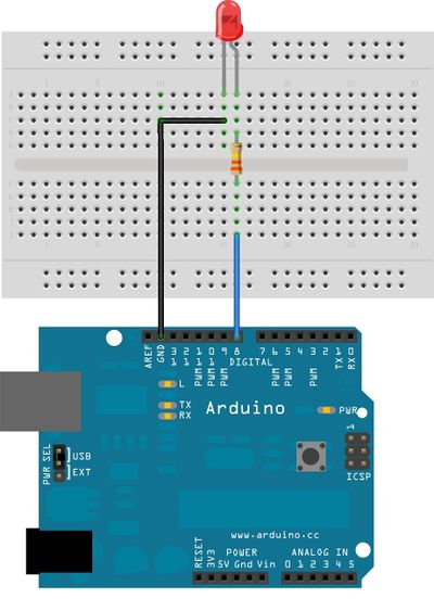
Connect an LED as shown here:
Getting Started With The Blynk App
1. Create a Blynk Account
After you download the Blynk App, you’ll need to create a New Blynk account. This account is separate from the accounts used for the Blynk Forums, in case you already have one.
We recommend using a real email address because it will simplify things later.
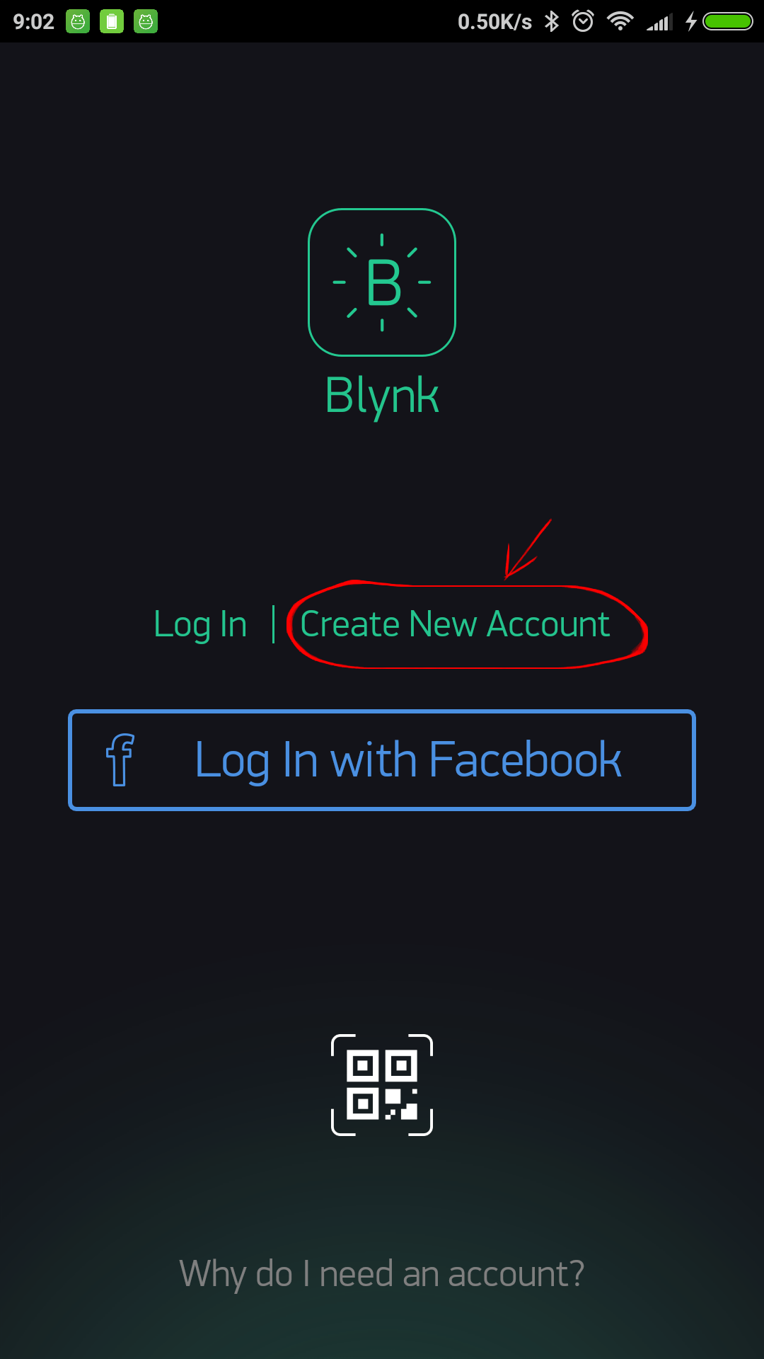
Why do I need to create an account?
An account is needed to save your projects and have access to them from multiple devices from anywhere. It’s also a security measure.
You can always set up your own Private Blynk Server and have full control.
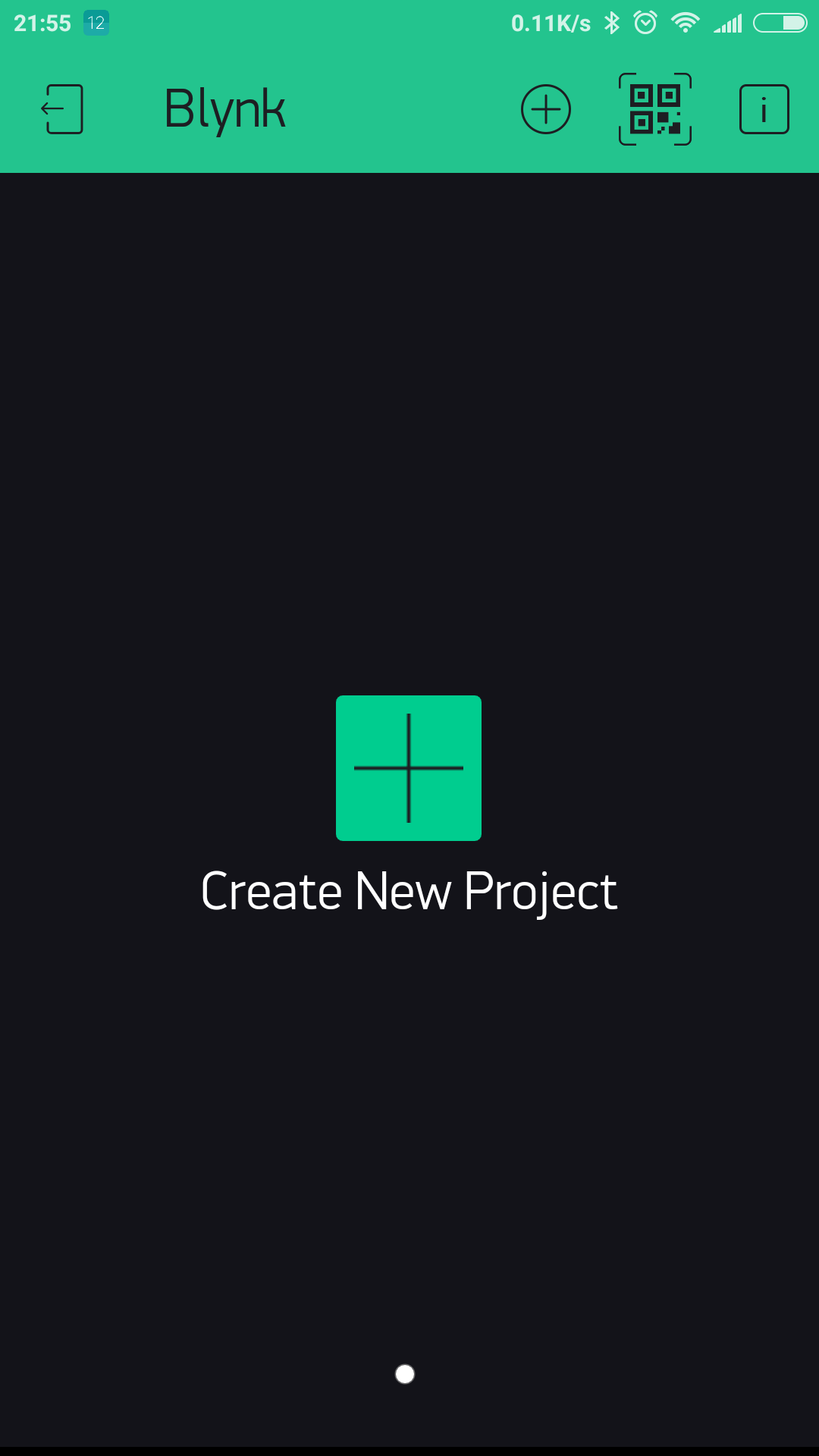
2. Create a New Project
After you’ve successfully logged into your account, start by creating a new project.
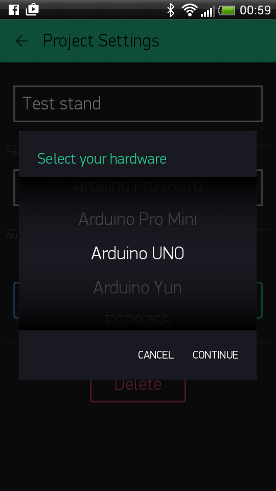
3. Choose Your Hardware
Select the hardware model you will use. Check out the list of supported hardware!
4. Auth Token
Auth Token is a unique identifier which is needed to connect your hardware to your smartphone. Every new project you create will have its own Auth Token. You’ll get Auth Token automatically on your email after project creation. You can also copy it manually. Click on devices section and selected required device :
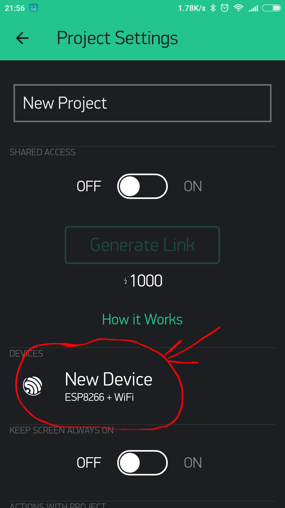
And you’ll see token :
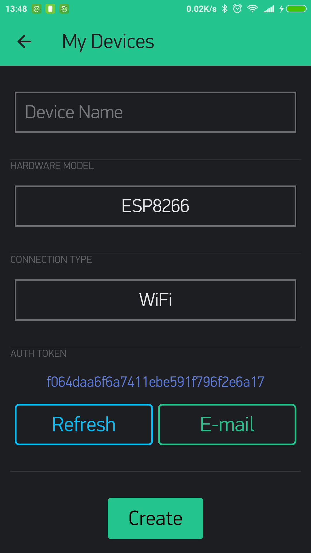
NOTE: Don’t share your Auth Token with anyone, unless you want someone to have access to your hardware.
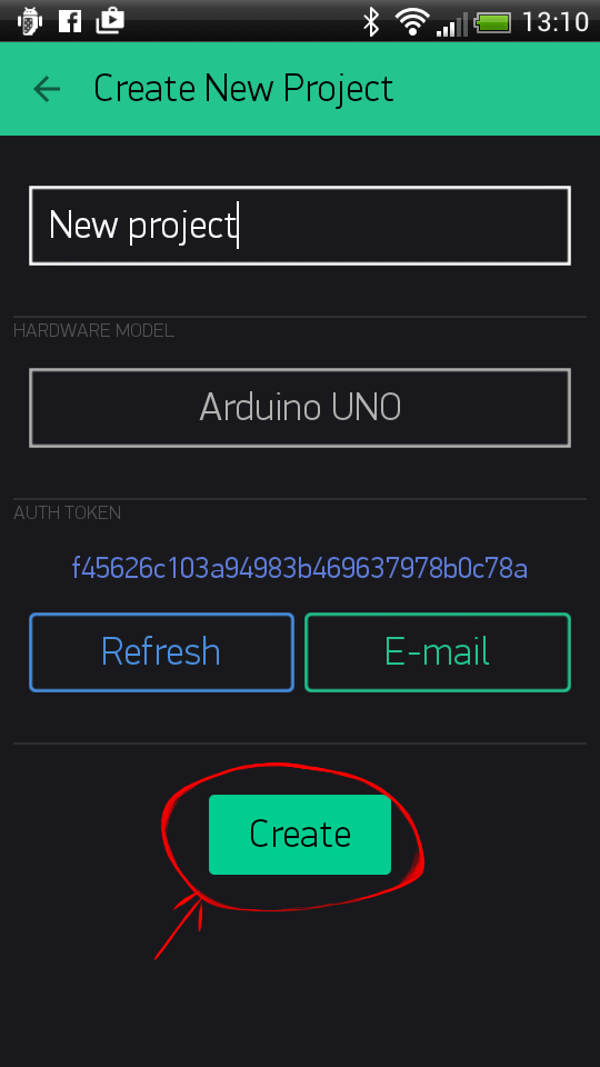
It’s very convenient to send it over e-mail. Press the e-mail button and the token will be sent to the e-mail address you used for registration. You can also tap on the Token line and it will be copied to the clipboard.
Now press the “Create” button.
5. Add a Widget
Your project canvas is empty, let’s add a button to control our LED.
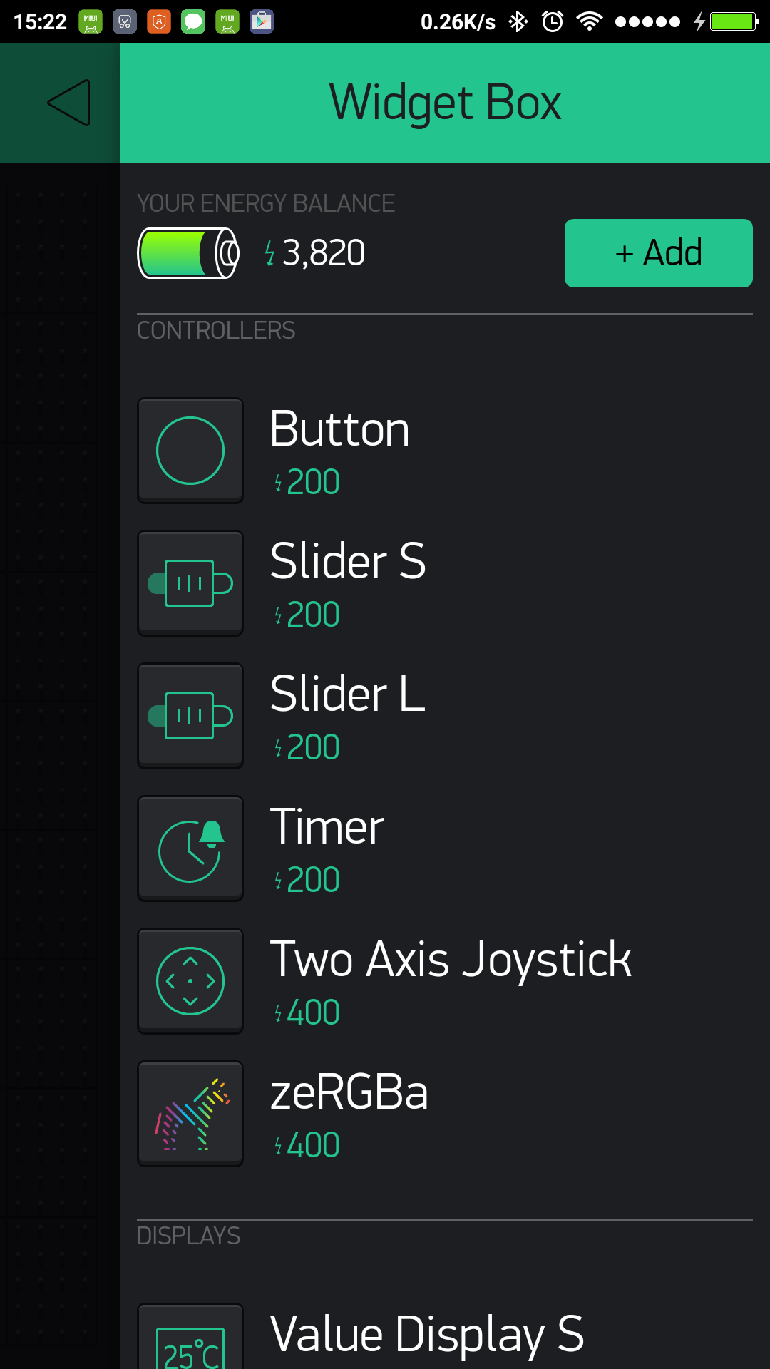
Tap anywhere on the canvas to open the widget box. All the available widgets are located here. Now pick a button.
Widget Box
Drag-n-Drop - Tap and hold the Widget to drag it to the new position.
Widget Settings - Each Widget has it’s own settings. Tap on the widget to get to them.
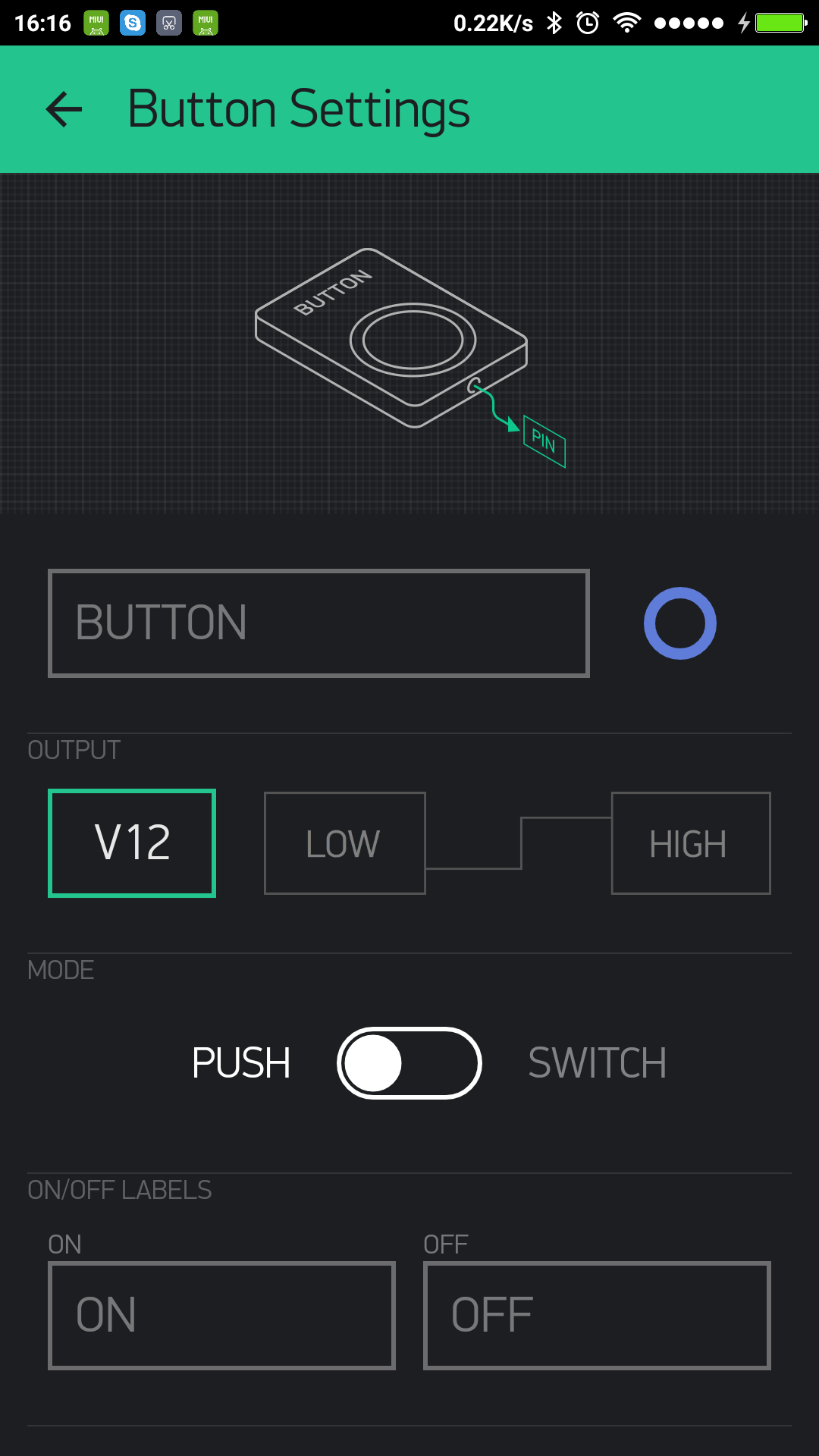
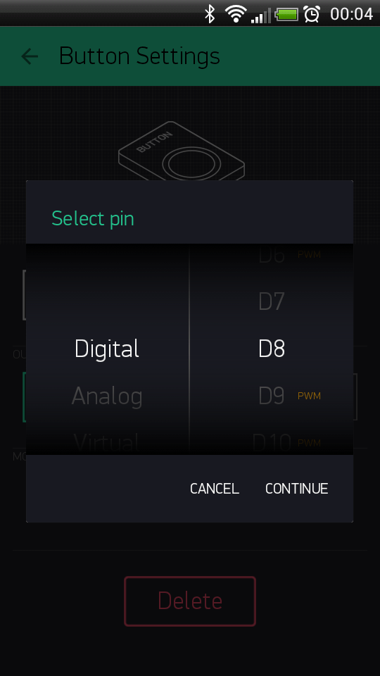
The most important parameter to set is PIN . The list of pins reflects physical pins defined by your hardware. If your LED is connected to Digital Pin 8 - then select D8 (D - stands for Digital).
6. Run The Project
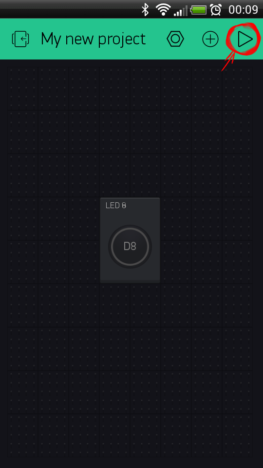
When you are done with the Settings - press the PLAY button. This will switch you from EDIT mode to PLAY mode where you can interact with the hardware. While in PLAY mode, you won’t be able to drag or set up new widgets, press STOP and get back to EDIT mode.
You will get a message saying “Arduino UNO is offline”. We’ll deal with that in the next section.
Getting Started With Hardware
How To Use an Example Sketch
You should by now have the Blynk Library installed on your computer. If not - click here.
Example sketches will help you get your hardware online quickly and major Blynk features.
Open the example sketch according to the hardware model or shield you are using.
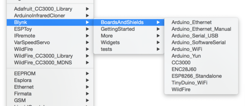
Let’s take a look at the example sketch for an Arduino UNO + Ethernet shield
#define BLYNK_PRINT Serial
#include <SPI.h>
#include <Ethernet.h>
#include <BlynkSimpleEthernet.h>

char auth[] = "YourAuthToken";

void setup()
{
  Serial.begin(9600); // See the connection status in Serial Monitor
  Blynk.begin(auth);  // Here your Arduino connects to the Blynk Cloud.
}

void loop()
{
  Blynk.run(); // All the Blynk Magic happens here...
}
Auth Token
In this example sketch, find this line:
char auth[] = "YourAuthToken";This is the Auth Token that you emailed yourself. Please check your email and copy it, then paste it inside the quotation marks.
It should look similar to this:
char auth[] = "f45626c103a94983b469637978b0c78a";Upload the sketch to the board and open Serial Terminal. Wait until you see something like this:
Blynk v.X.X.X
Your IP is 192.168.0.11
Connecting...
Blynk connected!
Congrats! You are all set! Now your hardware is connected to the Blynk Cloud!
Blynking
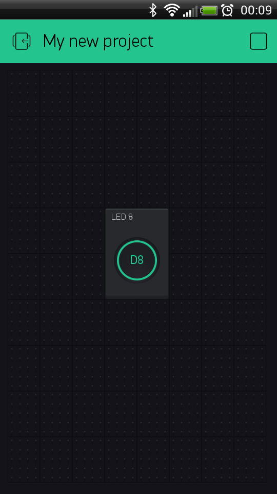
Go back to the Blynk App, push the button and turn the LED on and off! It should be Blynking.
Check out other example sketches.
Feel free to experiment and combine different examples together to create your own amazing projects.
For example, to attach an LED to a PWM-enabled Pin on your Arduino, set the slider widget to control the brightness of an LED. Just use the same steps described above.
Hardware set-ups
Arduino over USB (no shield)
If you don’t have any shield and your hardware doesn’t have any connectivity, you can still use Blynk – directly over USB :
Open Arduino Serial USB example and change Auth Token
 // You could use a spare Hardware Serial on boards that have it (like Mega)
 #include <SoftwareSerial.h>
 SoftwareSerial DebugSerial(2, 3); // RX, TX

 #define BLYNK_PRINT DebugSerial
 #include <BlynkSimpleStream.h>

 // You should get Auth Token in the Blynk App.
 // Go to the Project Settings (nut icon).
 char auth[] = "YourAuthToken";

 void setup()
 {
   // Debug console
   DebugSerial.begin(9600);

   // Blynk will work through Serial
   Serial.begin(9600);
   Blynk.begin(auth, Serial);
 }

 void loop()
 {
   Blynk.run();
 }
Run the script which is usually located in
/scriptsfolder:- Windows:
My Documents\Arduino\libraries\Blynk\scripts - Mac
User$/Documents/Arduino/libraries/Blynk/scripts
- Windows:
On Windows:
Open cmd.exe
Write your path to blynk-ser.bat folder. For example:
cd C:\blynk-library-0.3.1\blynk-library-0.3.1\scripts Run blynk-ser.bat file. For example : blynk-ser.bat -c COM4 (where COM4 is port with your Arduino)
And press “Enter”, press “Enter” and press “Enter”
On Linux and Mac:
Navigate to /scripts folder. For example:
cd User$/Documents/Arduino/libraries/Blynk/scriptsWhen inside this folder, run:
user:scripts User$ ./blynk-ser.shWarning: Do no close terminal window with running script.
In some cases you may also need to perform :
user:scripts User$ chmod +x blynk-ser.sh You may need also to run it with sudo
user:scripts User$ sudo ./blynk-ser.shThis is what you’ll see in Terminal app on Mac (usbmodem address can be different):
[ Press Ctrl+C to exit ]
/dev/tty.usbmodem not found.
Select serial port [ /dev/tty.usbmodem1451 ]:
Copy the serial port address: /dev/tty.usbmodem1451 and paste it back:
Select serial port [ /dev/tty.usbmodem1451 ]: /dev/tty.usbmodem1451After you press Enter, you should see an output similar to this:
Resetting device /dev/tty.usbmodem1451...
Connecting: GOPEN:/dev/tty.usbmodem1451,raw,echo=0,clocal=1,cs8,nonblock=1,ixoff=0,ixon=0,ispeed=9600,ospeed=9600,crtscts=0 <-> openssl-connect:blynk-cloud.com:9443,cafile=/Users/.../server.crt,nodelay
2015/10/03 00:29:45 socat[30438.2046857984] N opening character device "/dev/tty.usbmodem1451" for reading and writing
2015/10/03 00:29:45 socat[30438.2046857984] N opening connection to LEN=16 AF=2 45.55.195.102:9443
2015/10/03 00:29:45 socat[30438.2046857984] N successfully connected from local address LEN=16 AF=2 192.168.0.2:56821
2015/10/03 00:29:45 socat[30438.2046857984] N SSL connection using AES128-SHA
2015/10/03 00:29:45 socat[30438.2046857984] N starting data transfer loop with FDs [3,3] and [4,4]
NOTE: Arduino IDE may complain with “programmer is not responding”. You need to terminate script before uploading new sketch.
Additional materials:
- Tutorial: Control Arduino over USB with Blynk app. No shield required. Mac OS)
- How to control arduino (Wirelessly) with blynk via USB. Windows
- Instructables: Control Arduino with Blynk over USB
Raspberry Pi
- Connect your Raspberry Pi to the Internet and open it’s console.
Run this command (it updates your OS package repository to include the required packages):
curl -sL "https://deb.nodesource.com/setup_6.x" | sudo -E bash -Download and build Blynk JS library using npm:
 sudo apt-get update && sudo apt-get upgrade
 sudo apt-get install build-essential
 sudo apt-get install -g npm
 sudo npm install -g onoff
 sudo npm install -g blynk-library
Run Blynk test script (put your auth token):
blynk-client 715f8cafe95f4a91bae319d0376caa8cYou can write our own script based on examples
To enable Blynk auto restart for Pi, find
/etc/rc.localfile and add there:node full_path_to_your_script.js <Auth Token>
Additional materials:
- Instructables: Blynk on Javascript for Raspberry Pi, Intel Edison and others
- Instructables: Use DHT11/DHT12 sensors with Raspberry Pi and Blynk
Note: Instead of using Node.js, you can also build a C++ libarry version (same as Arduino, WiringPi-based) installation: - Library README for Linux - Blynk Community Topic: How-To Raspberry Pi - Video tutorial - Setting up Blynk and Raspberry Pi:
ESP8266 Standalone
You can run Blynk directly on the ESP8266!
Install the latest ESP8266 library for Arduino using this guide.
Example Sketch: ESP8266_Standalone
Additional materials:
- Instructables: ESP8266 ESP-12(Standalone)+ Blynk
- Instructables: ESP8266-12 standalone Blynk lm35 temperature sensor
Step-by-Step Tutorial in Russian language
NodeMCU
Please follow this detailed instruction. Or watch this Video tutorial.
Arduino + ESP8266 WiFi with AT commands
This connection type is not recommended for beginners.
If you would like to try it, please carefully read this help topic
Note: Some boards like Arduino UNO WiFi from Arduino.org, do not use AT commands (and do not provide relevant libraries), so this renders them unusable with Blynk.
Particle
Blynk works with the whole family of Particle products: Core, Photon and Electron
- Open Particle Web IDE.
- Go to the libraries.
- Search for Blynk in the Community Libraries and click on it
- Open
01_PARTICLE.INOexample - Click “use this example”
- Put your Auth Token here:
char auth[] = "YourAuthToken";and flash the Particle!
You can scan this QR code from the Blynk App and you’ll get a ready-to-test project for Particle Photon. Just put your Auth Token into the 01_PARTICLE.INO example.
Additional materials:
Blynk main operations
Virtual Pins
Blynk can control Digital and Analog I/O Pins on you hardware directly. You don’t even need to write code for it. It’s great for blinking LEDs, but often it’s just not enough…
We designed Virtual Pins to send any data from your microcontroller to the Blynk App and back.
Anything you connect to your hardware will be able to talk to Blynk. With Virtual Pins you can send something from the App, process it on microcontroller and then send it back to the smartphone. You can trigger functions, read I2C devices, convert values, control servo and DC motors etc.
Virtual Pins can be used to interface with external libraries (Servo, LCD and others) and implement custom functionality.
Hardware may send data to the Widgets over the Virtual Pin like this:
Blynk.virtualWrite(pin, "abc");
Blynk.virtualWrite(pin, 123);
Blynk.virtualWrite(pin, 12.34);
Blynk.virtualWrite(pin, "hello", 123, 12.34);
For more information about virtual pins, read this
Send data from app to hardware
You can send any data from Widgets in the app to your hardware.
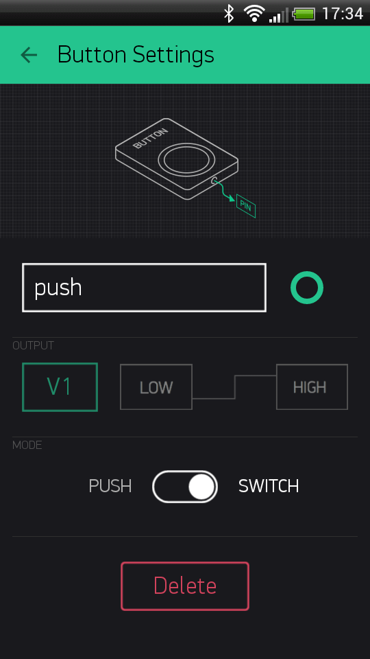
All Controller Widgets can send data to Virtual Pins on your hardware. For example, code below shows how to get values from the Button Widget in the App
BLYNK_WRITE(V1) //Button Widget is writing to pin V1
{
  int pinData = param.asInt();
}
When you press a Button, Blynk App sends 1 On the second click - it sends 0
This is how Button Widget is set up:
Full example sketch: Get Data
Sending array from Widget
Some Widgets (e.g Joystick, zeRGBa) have more than one output.
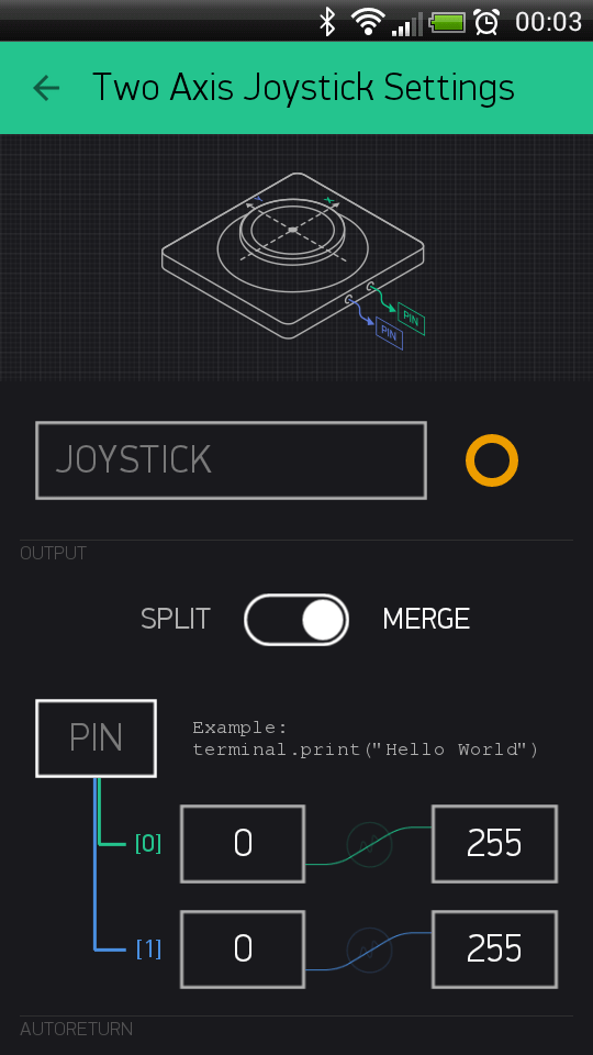
This output can be written to Virtual Pin as an array of values. On the hardware side - you can get any element of the array [0,1,2…] by using:
BLYNK_WRITE(V1) // Widget WRITEs to Virtual Pin V1
{
  int x = param[0].asInt(); // getting first value
  int y = param[1].asInt(); // getting second value
  int z = param[N].asInt(); // getting N value
}
Sketch: JoystickTwoAxis
Get data from hardware
There are two ways of pushing data from your hardware to the Widgets in the app over Virtual Pins.
Perform requests by Widget
- Using Blynk built-in reading frequency while App is active by setting ‘Reading Frequency’ parameter to some interval:
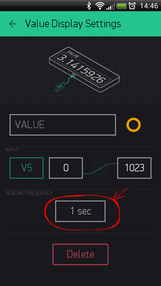
BLYNK_READ(V5) // Widget in the app READs Virtal Pin V5 with the certain frequency
{
  // This command writes Arduino's uptime in seconds to Virtual Pin V5
  Blynk.virtualWrite(5, millis() / 1000);
}
Sketch: PushDataOnRequest
Pushing data from hardware
If you need to PUSH sensor or other data from your hardware to Widget, you can write any logic you want. Just set the frequency to PUSH mode. Any command that hardware sends to Blynk Cloud is automatically stored on server and you get this info either with History Graph widget or with HTTP API.
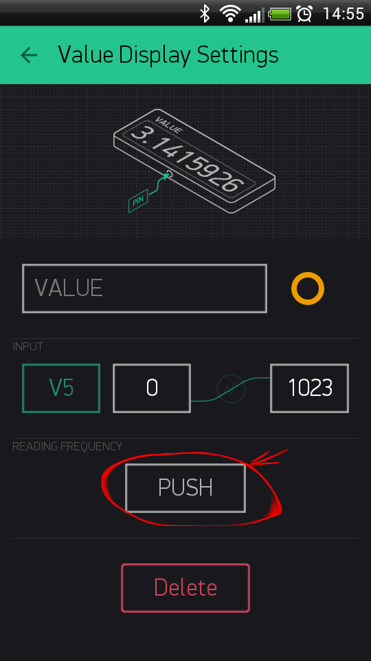
We recommend sending data in intervals and avoiding Flood Error. You can use timers like BlynkTimer. Please read instructions inside this example sketch for more details.
Here is how it can work:
#include <SPI.h>
#include <Ethernet.h>
#include <BlynkSimpleEthernet.h>

char auth[] = "YourAuthToken"; // Put your token here

BlynkTimer timer; // Create a Timer object called "timer"!

void setup()
{
  Serial.begin(9600);
  Blynk.begin(auth);

  timer.setInterval(1000L, sendUptime); //  Here you set interval (1sec) and which function to call
}

void sendUptime()
{
  // This function sends Arduino up time every 1 second to Virtual Pin (V5)
  // In the app, Widget's reading frequency should be set to PUSH
  // You can send anything with any interval using this construction
  // Don't send more that 10 values per second

  Blynk.virtualWrite(V5, millis() / 1000);
}

void loop()
{
  Blynk.run(); // all the Blynk magic happens here
  timer.run(); // BlynkTimer is working...
}
Sketch: PushData
State syncing
For hardware
If your hardware looses Internet connection or resets, you can restore all the values from Widgets in the Blynk app.
BLYNK_CONNECTED() {
    Blynk.syncAll();
}

//here handlers for sync command
BLYNK_WRITE(V0) {
   ....
}
The Blynk.syncAll() command restores all the Widget’s values based on the last saved values on the server.
All analog and digital pin states will be restored. Every Virtual Pin will perform BLYNK_WRITE event.
WARNING: if pin is empty and wasn’t initialized - hardware will not get any response for those pin during sync.
You can also update a single Virtual Pin value by calling Blynk.syncVirtual(V0) or you can update several pins with Blynk.syncVirtual(V0, V1, V2, ...).
You can also use server to store any value without widget. Just call Blynk.virtualWrite(V0, value).
Storing single value on server
Storing multiple values on server
For app
If you need to keep your hardware in sync with Widgets’ state even if app is offline use Blynk.virtualWrite.
Imagine you have a LED Widget connected to the Virtual Pin V1 in the app, and a physical button attached to your hardware.
When you press a physical button, you would expect to see updated state of the LED Widget in the app.
To achieve that you need to send Blynk.virtualWrite(V1, 255) when a physical button gets pressed.
Represent physical button state via LED widget with interrupts
Represent physical button state via LED widget with polling
Represent physical button state via Button widget with polling
Control of multiple devices
Blynk app has support of multiple devices. That means you can assign any widget to specific device with own auth token. For example - you may have button on V1 that controls wi-fi bulb A and another button on V1 that controls wi-fi bulb B. In order to do this you need more than 1 device within your project. To achieve this please go to project settings and click on “Devices” section :
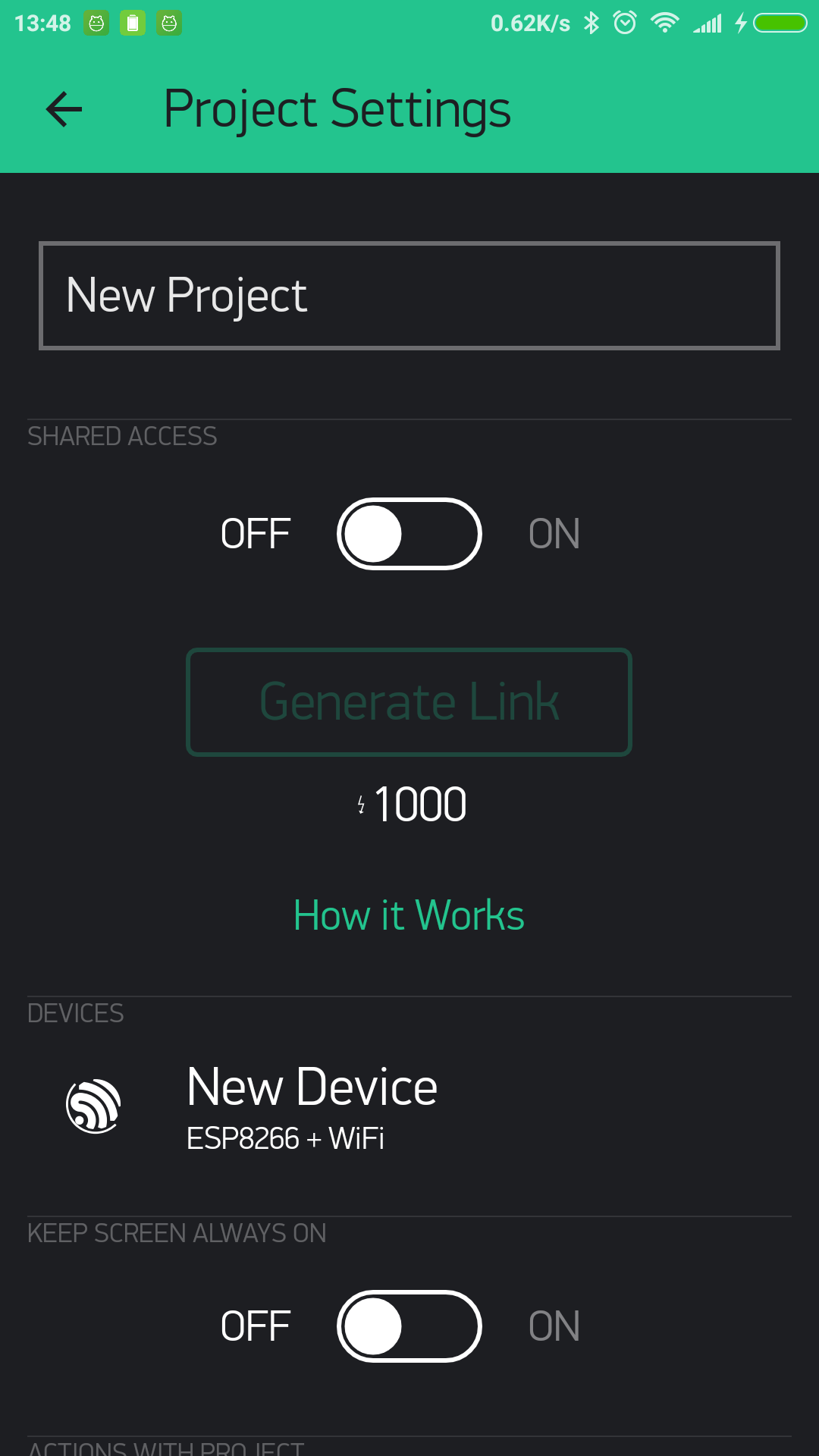
You’ll see list of devices :
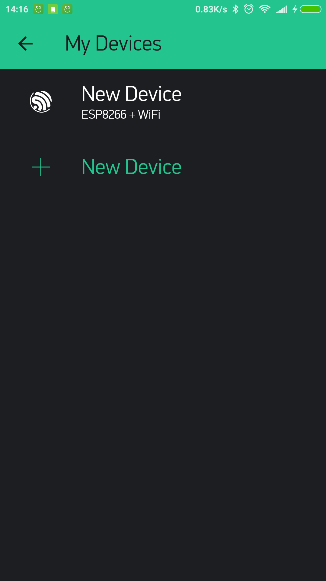
So you can add new device :
.png)
After above steps, every widget will have one more field “Target” :
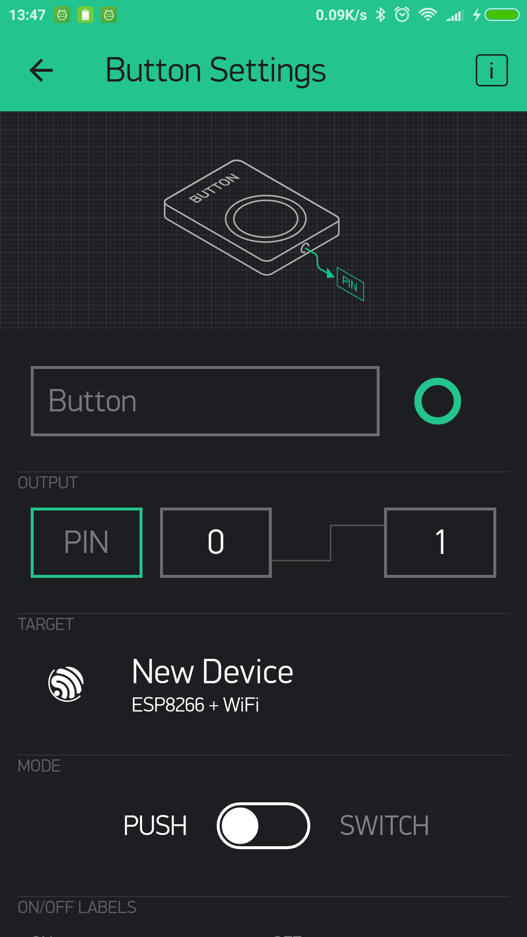
Now you need to assign widget to device and after that widget will control only this specific device.
That’s it! Now you need to upload sketches with correct Auth Tokens to your hardware.
Tags
Tags feature allows you to group multiple devices. Tags are very useful in case you want to control few devices with 1 widget. For example, imagine a case when you have 3 smart bulbs and you want to turn on all those bulbs with one single click. You need to assign 3 devices to 1 tag and assign tag to button. That’s it.
Tag widgets also support state syncing. So you can get state of widget from your hardware. However you can’t update state of such widgets from hardware.
Devices online status
Blynk app has support for online statuses for multiple devices.
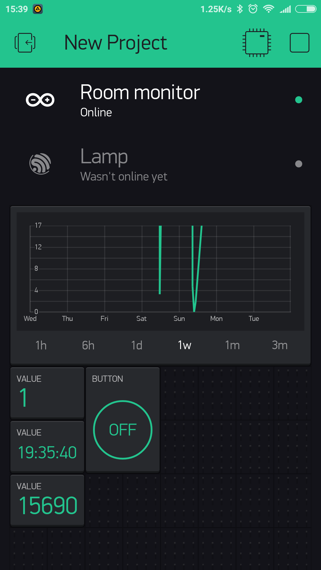
In ideal world when device closes tcp connection with some connection.close() - connected server will get notification
regarding closed connection. So you can get instant status update on UI. However in real world this mostly exceptional situation.
In majority of cases there is no easy and instant way to find out that connection is not active anymore.
That’s why Blynk uses HEARTBEAT mechanism. With this approach hardware periodically sends ping command with predefined
interval (10 seconds by default, BLYNK_HEARTBEAT property).
In case hardware don’t send anything within 10 seconds server waits additional 5 seconds and after that connection
assumed to be broken and closed by server. So on UI you’ll see connection status update only after 15 seconds when it is
actually happened.
You can also change HEARTBEAT interval from hardware side via Blynk.config. In that case newHeartbeatInterval * 2.3 formula will be applied. So in case you you decided to set HEARTBEAT interval to
5 seconds. You’ll get notification regarding connection with 11 sec delay in worst case.
Project Settings
Every project has it’s own settings:
- Theme - switch between the Light and Black Blynk Theme (Business accounts have wider choice);
- Keep screen always on - allows you to use the Blynk app without going to the sleep mode (usually all mobile devices do that);
- Send app connected command - with this option enabled the server will send “App Connected” and “App Disconnected” commands to your hardware when your Blynk app goes online/offline. Usage example;
- Do not show offline notifications - right now, for debugging purposes, every time your hardware goes offline - the Blynk Server will notify you with popup in the app about that. However, when debugging is not needed or the Blynk app is used only via HTTP/S this notifications are meaningless. So this switch allows you to turn off this popups. Also this switch turns off the Push notification “Notify when offline” option.
Change Widget properties
Changing some of the widget properties from hardware side is also supported.
For example, you can change the color of LED widget based on a condition:
//change LED color
Blynk.setProperty(V0, "color", "#D3435C");

//change LED label
Blynk.setProperty(V0, "label", "My New Widget Label");

//change MENU labels
Blynk.setProperty(V0, "labels", "Menu Item 1", "Menu Item 2", "Menu Item 3");
Set Property for single value field
Set Property for multi value field
NOTE : Changing these parameters work only for widgets attached to Virtual pins (analog/digital pins won’t work).
Four widget properties are supported - color, label, min, max for all widgets :
label is string for label of all widgets.
color is string in HEX format (in the form: #RRGGBB,
where RR (red), GG (green) and BB (blue) are hexadecimal values between 00 and FF). For example :
#define BLYNK_GREEN     "#23C48E"
#define BLYNK_BLUE      "#04C0F8"
#define BLYNK_YELLOW    "#ED9D00"
#define BLYNK_RED       "#D3435C"
#define BLYNK_DARK_BLUE "#5F7CD8"min, max - minimum and maximum values for the widget (for example range for the Slider).
This numbers may be float.
On firmware side, widget objects also support setLabel() and setColor() functions.
Widget specific properties:
Button
onLabel / offLabel is string for ON/OFF label of button;
Styled Button
onLabel / offLabel is string for ON/OFF label of button;
onColor / offColor is string in HEX format for ON/OFF colors of the button;
onBackColor / offBackColor is string in HEX format for ON/OFF colors of the button background.
Music Player
isOnPlay is boolean accepts true/false.
Blynk.setProperty(V0, "isOnPlay", "true");Menu
labels is list of strings for Menu widget selections;
Blynk.setProperty(V0, "labels", "label 1", "label 2", "label 3");Video Streaming
Blynk.setProperty(V1, "url", "http://my_new_video_url");Step
Blynk.setProperty(V1, "step", 10);Image
Blynk.setProperty(V1, "opacity", 50); // 0-100%Blynk.setProperty(V1, "scale", 30); // 0-100%Blynk.setProperty(V1, "rotation", 10); //0-360 degreesalso, you can fully replace the list of images from the hardware:
Blynk.setProperty(V1, "urls", "https://image1.jpg", "https://image2.jpg");or you can change individual image by it index:
Blynk.setProperty(V1, "url", 1, "https://image1.jpg");You can also change widget properties via HTTP API.
Limitations and Recommendations
Don’t put
Blynk.virtualWriteand any otherBlynk.*command insidevoid loop()- it will cause lot’s of outgoing messages to our server and your connection will be terminated;We recommend calling functions with intervals. For example, use BlynkTimer
Avoid using long delays with
delay()– it may cause connection breaks;If you send more than 100 values per second - you may cause Flood Error and your hardware will be automatically disconnected from the server;
Be careful sending a lot of
Blynk.virtualWritecommands as most hardware is not very powerful (like ESP8266) so it may not handle many requests.
Widgets
Widgets are interface modules. Each of them performs a specific input/ output function when communicating with the hardware.
There are 4 types of Widgets:
- Controllers - used to send commands that control your hardware
- Displays - used for data visualization from sensors and other sources;
- Notifications - send messages and notifications;
- Interface - widgets to perform certain GUI functions;
- Other - widgets that don’t belong to any category;
Each Widget has it’s own settings. Some of the Widgets (e.g. Bridge) just enable functionality and they don’t have any settings.
Common Widget Settings
Pin Selector
This is one of the main parameters you need to set. It defines which pin to control or to read from.

Digital Pins - represent physical Digital IO pins on your hardware. PWM-enabled pins are marked with the ~ symbol
Analog Pins - represent physical Analog IO pins on your hardware
Virtual Pins - have no physical representation. They are used to transfer any data between Blynk App and your hardware. Read more about Virtual Pins here.
Data Mapping
In case you want to map incoming values to specific range you may use mapping button:
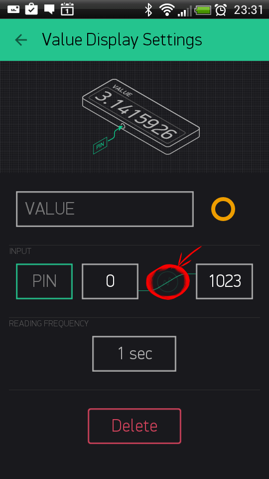
Let’s say your sensor sends values from 0 to 1023. But you want to display values in a range 0 to 100 in the app. When Data Mapping enabled, incoming value 1023 will be mapped to 100.
SPLIT/MERGE
Some of the Widgets can send more than one value. And with this switch you can control how to send them.
SPLIT: Each of the parameters is sent directly to the Pin on your hardware (e.g D7). You don’t need to write any code.
NOTE: In this mode you send multiple commands from one widget, which can reduce performance of your hardware.
Example: If you have a Joystick Widget and it’s set to D3 and D4, it will send 2 commands over the Internet:
  digitalWrite(3, value);
  digitalWrite(4, value);
MERGE: When MERGE mode is selected, you are sending just 1 message, consisting of array of values. But you’ll need to parse it on the hardware.
This mode can be used with Virtual Pins only.
Example: Add a zeRGBa Widget and set it to MERGE mode. Choose Virtual Pin V1
  BLYNK_WRITE(V1) // There is a Widget that WRITEs data to V1
  {
    int r = param[0].asInt(); // get a RED channel value
    int g = param[1].asInt(); // get a GREEN channel value
    int b = param[2].asInt(); // get a BLUE channel value
  }
Decimals
Defines how many decimals you would like to see when moving a Slider. When “No Fraction” is chosen, slider will only send integer values with no decimals. “1 digit” means that values will look like 1.1, 1.2, …, 2.0, etc.
Send On Release
This option allows you to optimize data traffic on your hardware.
For example, when you move joystick widget, commands are streamed to the hardware, during a single joystick move you can send dozens of commands. There are use-cases where it’s needed, however creating such a load may lead to hardware overload and reset. Send On Release is a recommended setting for majority of applications. This is also a default setting.
Write interval
Similar to “Send on Release” option. However, it allows you to stream values to your hardware within certain interval. For example, setting write interval to 100 ms means that while you move the slider, only 1 value will be sent to hardware within 100 ms period. This option is also used to optimize data traffic flow to your hardware.
Color gradient
When you choose gradient, it affects the color of widget elements based on invoming values.
For example: You set Gauge Widget with Min and Max parameters of 0-100, and choose green-yellow-red gradient. When hardware sends:
- 10, Gauge will change it’s color to green color
- 50 will change Gauge to yellow color
- 80 will change Gauge to red color
There are 2 types of gradients you can choose from: - Warm: Green - Orange - Red; - Cold: Green - Blue - Violet;
Controllers
Button
Works in push or switch modes. Allows to send ON and OFF (LOW/HIGH) values. Button sends 1 (HIGH) on press and sends 0 (LOW) on release.

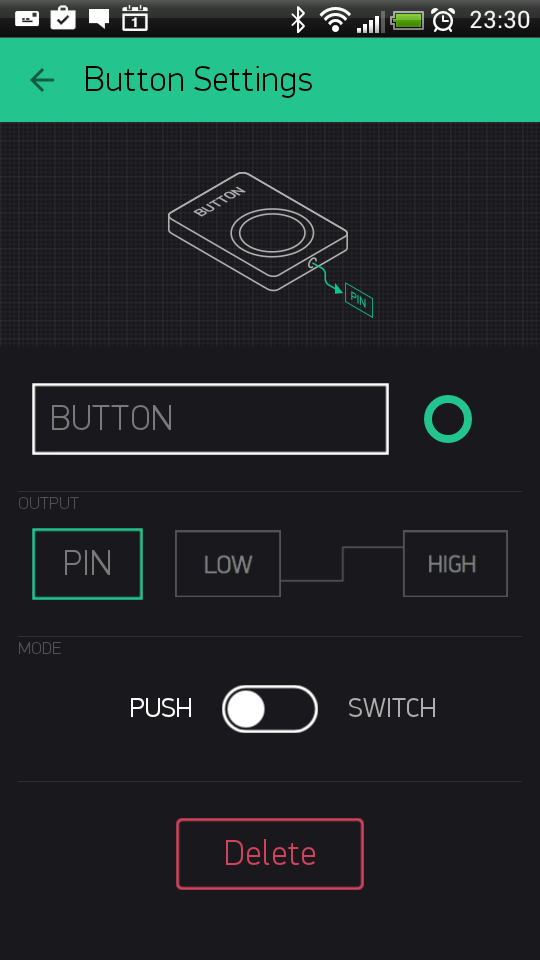
Sketch: BlynkBlink
Slider
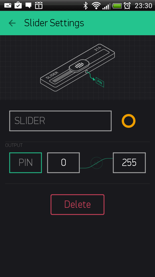
Similar to potentiometer. Allows to send values between in a given MIN/MAX range.
Sketch: BlynkBlink
Timer
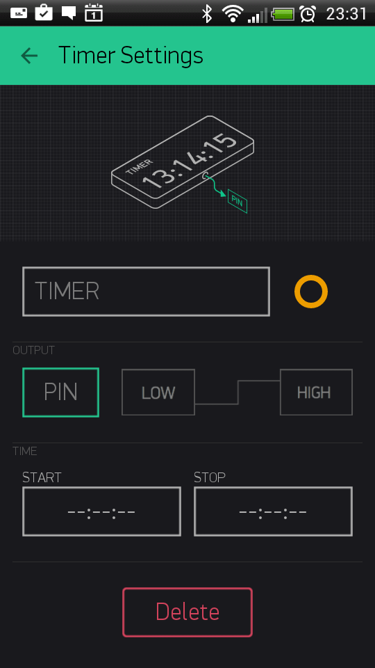
Timer triggers actions at a specified time. Even if smartphone and app is offline. Start time sends 1 (HIGH). Stop time sends 0 (LOW).
Recent Android version also has improved Timer within Eventor widget. With Eventor Time Event you can assign multiple timers on same pin, send any string/value, select days and timezone. It is recommended to use Eventor over Timer widget. However Timer widget is still suitable for simple timer events.
NOTE: The timer widget rely on the server time and not your phone time. Sometimes the phone time may not match the server time.
Sketch: Timer
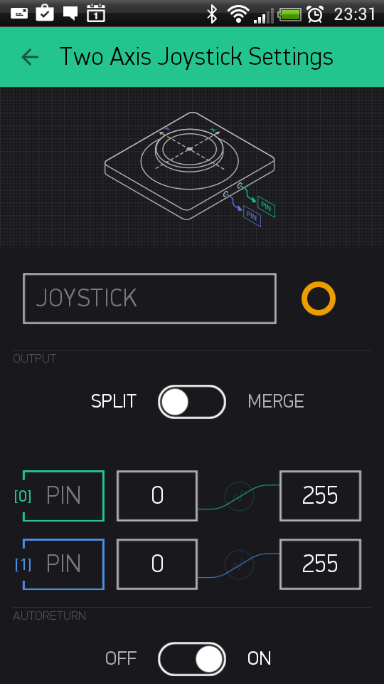
Joystick
Control servo movements in 4 directions
Settings:
SPLIT/MERGE modes - read here
Rotate on Tilt
When it’s ON, Joystck will automatically rotate if you use your smartphone in landscape orientation
- Auto-Return
-
When it’s OFF, Joystick handle will not return back to center position. It will stay where you left it.
Sketch: JoystickTwoAxis
zeRGBa
zeRGBa is a usual RGB color picker + brightness picker
Settings:
- SPLIT: Each of the parameters is sent directly to the Pin on your hardware (e.g D7). You don’t need to write any code.
NOTE: In this mode you send multiple commands from one widget, which can reduce performance of your hardware.
Example: If you have a zeRGBa Widget and it’s set to D1, D2, D3 it will send 3 commands over the Internet:
digitalWrite(1, r);
digitalWrite(2, g);
digitalWrite(3, b);- MERGE: When MERGE mode is selected, you send 1 message with an array of values inside. You would need to parse the message on the hardware.
This mode can be used with Virtual Pins only.
Example: Add a zeRGBa Widget and set it to MERGE mode. Choose Virtual Pin V1.
BLYNK_WRITE(V1) // zeRGBa assigned to V1
{
    // get a RED channel value
    int r = param[0].asInt();
    // get a GREEN channel value
    int g = param[1].asInt();
    // get a BLUE channel value
    int b = param[2].asInt();
}
Step Control
Step Control is used to set granular values with a given step
2 buttons are assigned to 1 pin. One button increments the value, another one decrements it.
Send Step option allows you to send step value to hardware instead of actual value of step widget. Loop value option allows you to reset step widget to start value when maximum value is reached.
Sketch: Basic Sketch
Displays
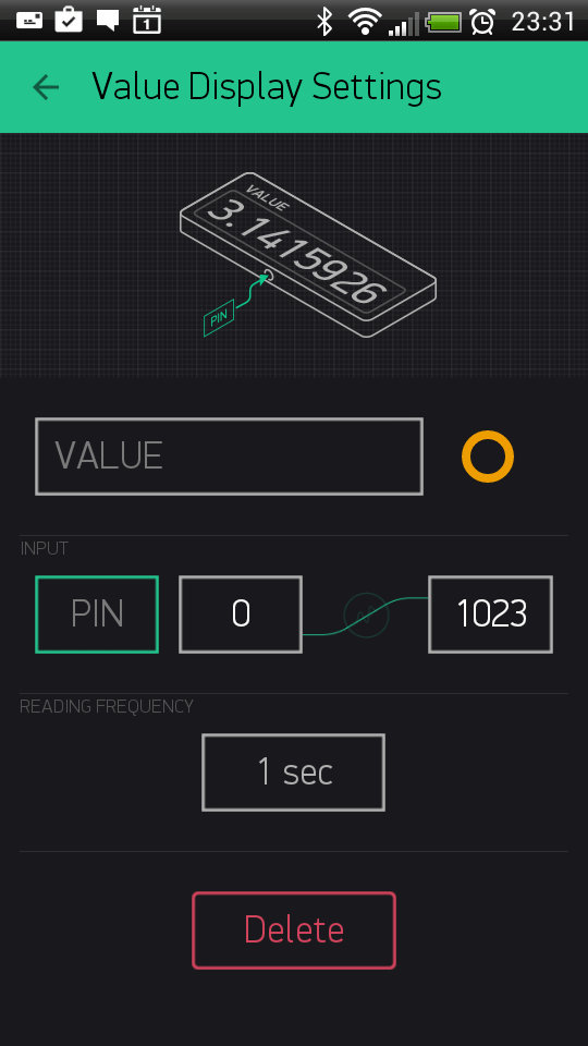
Value Display
Displays incoming data.

Sketch: BlynkBlink
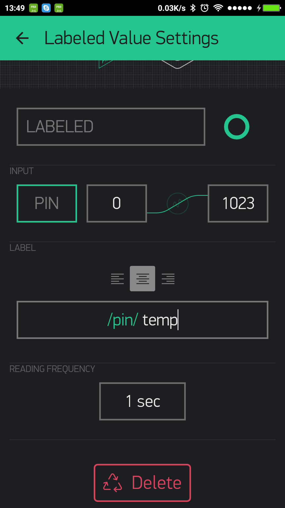
Labeled Value
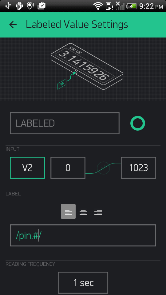
Displays incoming data in a formatted wayt. It is a better version of ‘Value Display’ where you can add suffixes and prefixes on the app side, with no coding on the hardware.

Sketch: BlynkBlink
Formatting options
For example: your sensor sends vaule of 12.6789 to Blynk application. Next formatting options are supported:
/pin/ - displays the value without formatting (12.6789)
/pin./ - displays the rounded value without decimal part (13)
/pin.#/ - displays the value with 1 decimal digit (12.7)
/pin.##/ - displays the value with two decimal places (12.68)
LED
A simple LED for indication. You need to send 0 in order to turn LED off. And 255 in order to turn LED on. Or just use Blynk API as described below:
WidgetLED led1(V1); //register to virtual pin 1
led1.off();
led1.on();
All values between 0 and 255 will change LED brightness:
WidgetLED led2(V2);
led2.setValue(127); //set brightness of LED to 50%.
Sketch: LED
Gauge
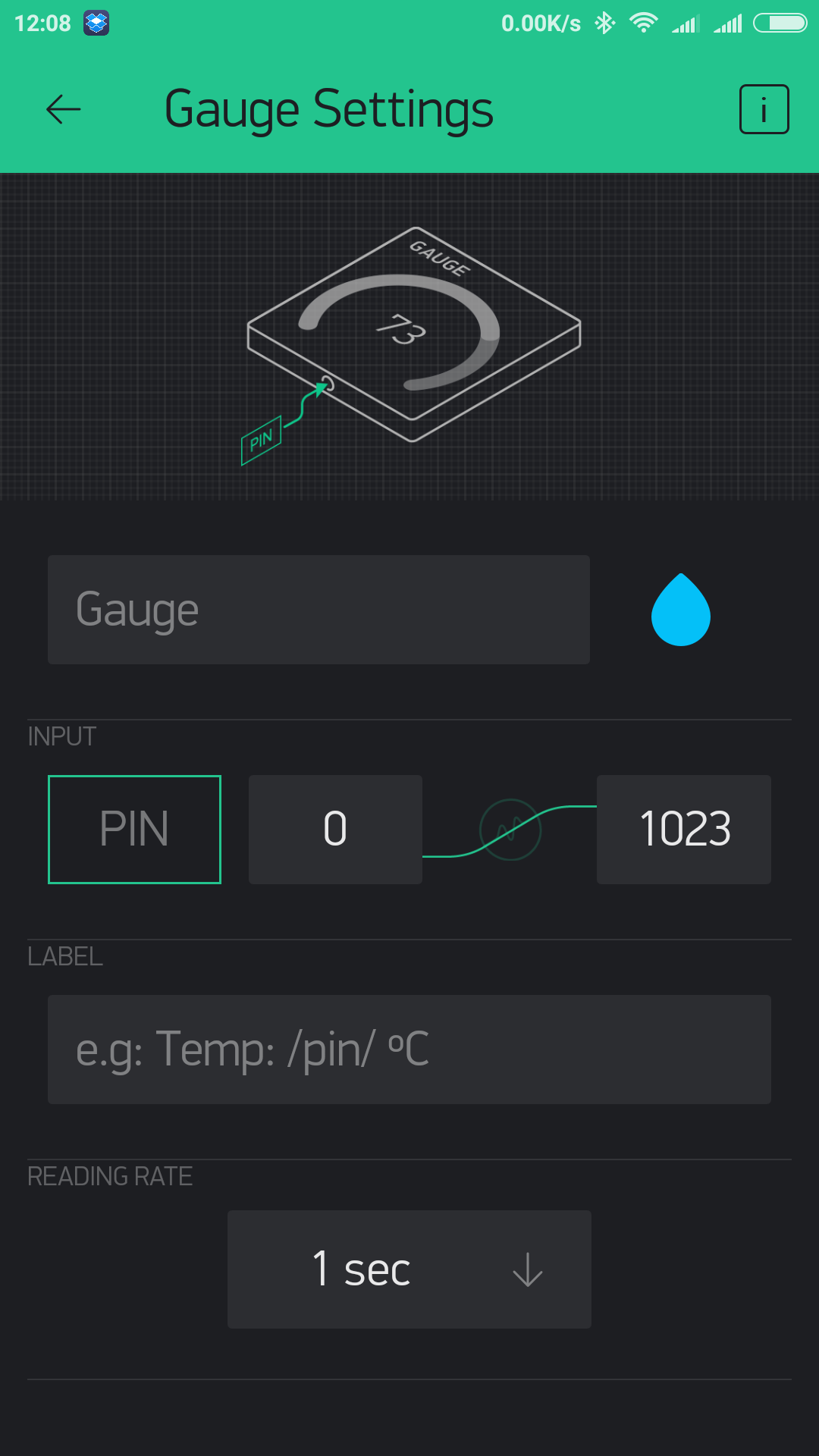
Visual display of numeric values.
Sketch: BlynkBlink
Formatting options
For example: your sensor sends vaule of 12.6789 to Blynk application. Next formatting options are supported:
/pin/ - displays the value without formatting (12.6789)
/pin./ - displays the rounded value without decimal part (13)
/pin.#/ - displays the value with 1 decimal digit (12.7)
/pin.##/ - displays the value with two decimal places (12.68)
LCD
This is a regular 16x2 LCD display made in our secret facility in China.
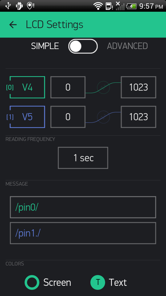
SIMPLE / ADVANCED MODE
Commands
You need to use special commands with this widget:
lcd.print(x, y, "Your Message");Where x is a symbol position (0-15), y is a line id (0 or 1),
lcd.clear();
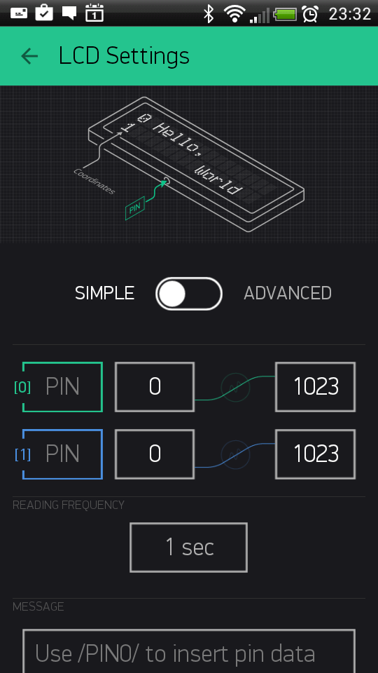
Sketch: LCD Advanced Mode Sketch: LCD Simple Mode Pushing Sketch: LCD Simple Mode Reading
Formatting options
For example: your sensor sends vaule of 12.6789 to Blynk application. Next formatting options are supported:
/pin/ - displays the value without formatting (12.6789)
/pin./ - displays the rounded value without decimal part (13)
/pin.#/ - displays the value with 1 decimal digit (12.7)
/pin.##/ - displays the value with two decimal places (12.68)
SuperChart
SuperChart is used to visualise live and historical data. You can use it for sensor data, for binary event logging and more.
To use SuperChart widget you would need to push the data from the hardware with the desired interval by using timers.
Here is a basic example for data pushing.
Interactions:
Switch between time ranges and Live mode
Tap time ranges at the bottom of the widget to change time rangesTap Legend Elements to show or hide datastreams
Tap’n’hold to view timestamp and corresponding values
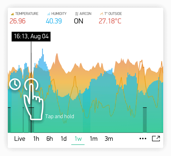
- Quick swipe from left to right to reveal previous data
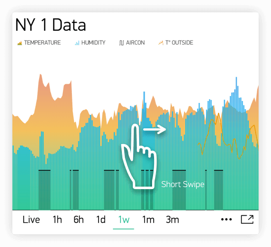
Then you can then scroll data back and forward within the given time range.
- Full Screen Mode
Press this button to open Full Screen view in landscape orientation:
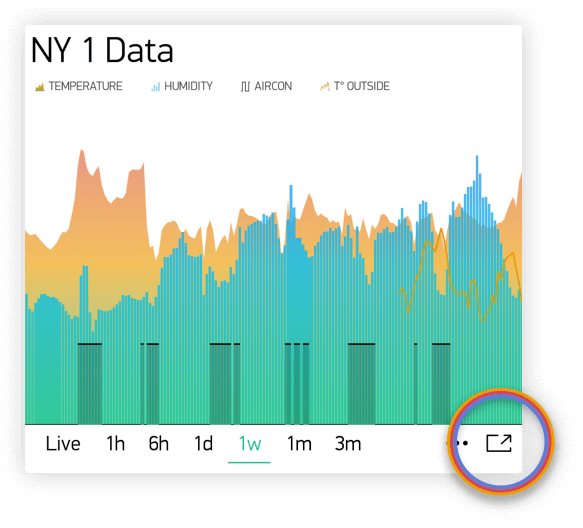
Simply rotate the phone back to portrait mode. Chart should rotate automagically. In full screen view you will see X (time) and multiple Y scales. Full Screen Mode can be disabled from widget Settings.
- Menu Button
Menu button will open additional functions:- Export to CSV
- Erase Data on the server
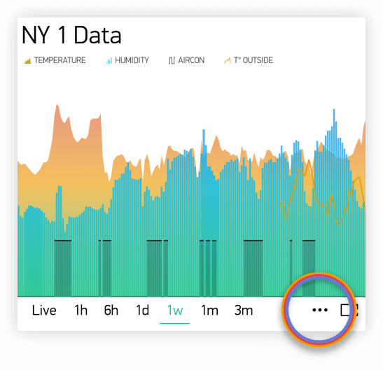
SuperChart Settings:
- Chart Title
- Title Font Size You have a choice of 3 font sizes
- Title Alignment Choose chart title alignment. This setting also affects Title and Legend position on the Widget.
- Show x-axis (time) Select it if you want to show the time label at the bottom of your chart.
Time ranges picker Allows you to select required periods (
15m,30m,1h,3h, …) and resolution for your chart. Resolution defines how precise your data is. Right now chart supports 2 types of resolutionstandardandhigh. Resolution also depends on the selected period. For example,standardresolution for1dmeans you’ll get 24 points per day (1 per hour), withhighresolution you’ll get for1d1440 points per day (1 per minute).Datastreams - add datastreams (read below how to configure datastreams)
Datastream Settings
Widget supports up to 4 Datastreams. Press Datastream Settings Icon to open Datastream Settings.
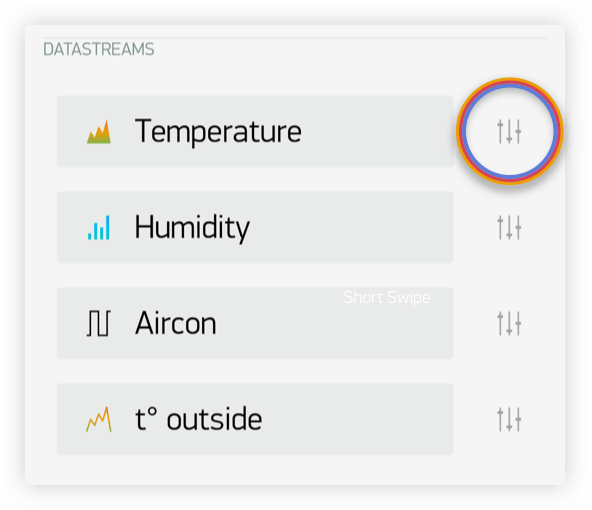
Design: Choose available types of Chart:
- Line
- Area
- Bar
- Binary (anchor LINK to binary)
Color: Choose solid colors or gradients
Source and input: You can use 3 types of Data source:
1. Virtual Pin Choose the desired Device and Virtual Pin to read the data from.
2. Tags SuperChart can aggregate data from multiple devices using built-in aggregation functions. For example, if you have 10 Temperature sensors sending temperature with the given period, you can plot average value from 10 sensors on the widget.
To use Tags:
- Add Tag to every device you want to aggregate data from.
- Push data to the same Virtual Pin on every device. (e.g.
Blynk.virtualWrite (V0, temperature);) - Choose Tag as a source in SuperChart Widget and use the pin where the data is coming to (e.g V0)
Functions available:
- SUM, will summarize all incoming values to the specified Virtual Pin across all devices tagged with the chosen tag
- AVG, will plot average value
- MED, will find a median value
- MIN, will plot minimum value
- MAX will plot maximum value
☝️ IMPORTANT: Tags are not working in Live Mode.
- Device Selector If you add Device Selector Widget to your project, you can use it as a source for SuperChart. In this case, when you change the device in Device Selector, chart will be updated accordingly
Y-Axis Settings
There are 4 modes of how to scale data along the Y axis
Auto
Data will be auto-scaled based on min and max values of the given time period. This is nice option to start with.Values
When this mode is selected, Y scale will be set to the values you choose. For example, if your hardware sends data with values varying from -100 to 100, you can set the chart to this values and data will be rendered correctly.
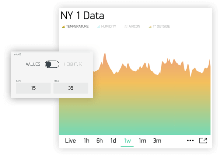
You may also want to visualize the data within some specific range. Let’s say incoming data has values in the range of 0-55, but you would like to see only values in the range 30-50. You can set it up and if values are out of Y scale you configured, chart will be cropped
- % of Height
This option allows you to auto-scale incoming data on the widget and position it the way you want. In this mode, you set up the percentage of widget height on the screen, from 0% to 100%.
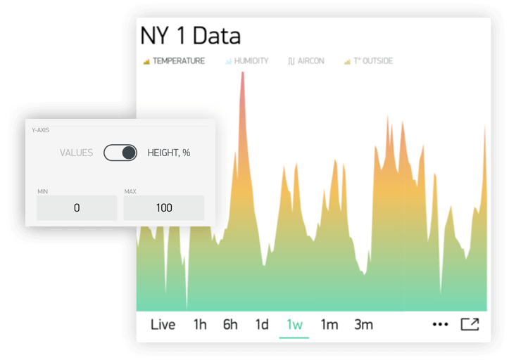
If you set 0-100%, in fact it’s a full auto-scale. No matter in which range the data is coming,
it will be always scaled to the whole height of the widget.
If you set it to 0-25%, then this chart will only be rendered on 1/4 of the widget height:
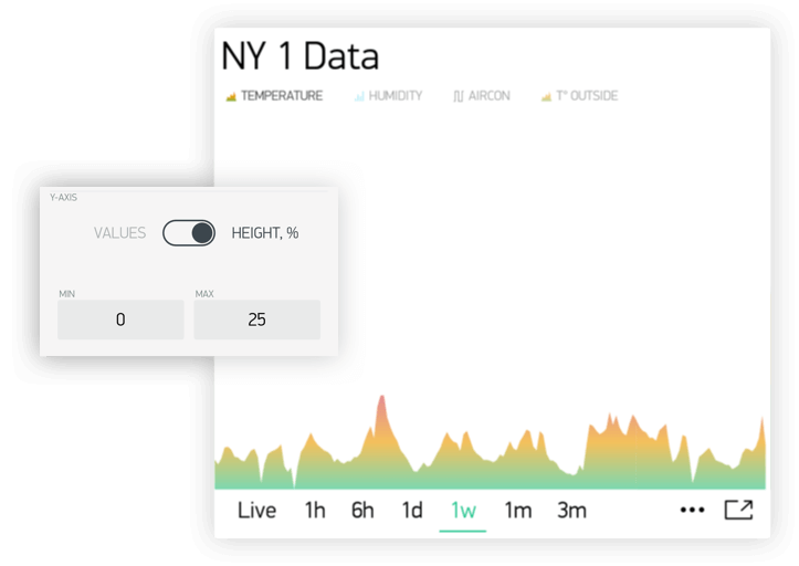
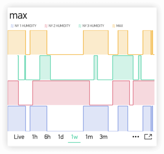
This setting is very valuable for Binary Chart or for visualizing a few datastreams on the same chart in a different way.
- Delta
While data stays within the given Delta value, chart will be auto-scaled within this range. If delta exceeds the range, chart will be auto-scaled to min/max values of the given period.
Suffix:
Here you can specify a suffix that will be shown during the Tap’n’hold
Decimals
Defines the formatting of the graph value when you Tap’n’hold the graph. Possible options are: #, #.#, #.##, etc.
Connect Missing Data Points
If this switch is ON, then SuperChart will connect all the dots even if there was no data
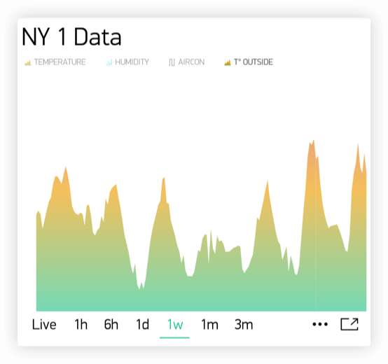
If it’s set to OFF, then you will see gaps in case there was no data.
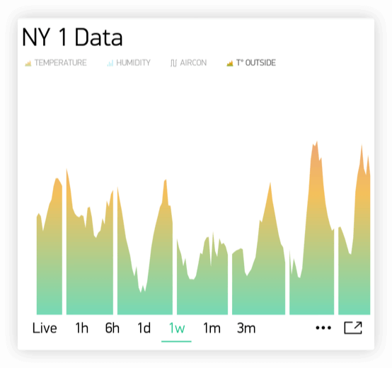
Binary Chart Settings
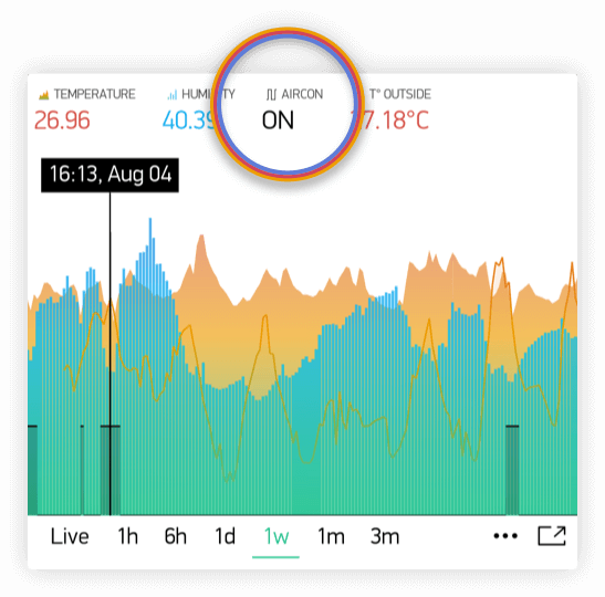
This type of chart is useful to plot binary data, for example when unit was ON or OFF, or when motion was detected or when certain threshold was reached.
You need to specify a FLIP point, which is the point where incoming data will be turned into TRUE or FALSE state.
For example, you send the data in the range of 0 to 1023. If you set 512 as a FLIP point, then everything above 512 (excluding 512) will be recorded as TRUE, any value below 512 (including 512) will be FALSE.
Another example, if you send 0 and 1 and set 0 as a FLIP point, then 1 will be TRUE, 0 will be FALSE
State Labels:
Here you can specify how TRUE/FALSE should be shown in Tap’n’Hold mode.
For example, you can set to TRUE to “Equipment ON” label, FALSE to “Equipment OFF”.
Superchart supports currently 2 types of granularity:
- Minute granularity -
1h,6h,1d; - Hour granularity -
1w,1m,3m;
This means that minimum chart update interval is 1 minute for 1h, 6h, 1d periods.
1 hour for 1w, 1m and 3m periods.
As Blynk Cloud is free to use we have a limit on how many data you can store. At the moment Blynk Cloud accepts
1 message per minute per pin. In case you send your data more frequently your values will be averaged. For example,
in case you send value 10 at 12:12:05 and than again 12 at 12:12:45 as result in chart you’ll see
value 11 for 12:12.
In order to see data in chart you need to use either widgets with “Frequency reading” interval (in
that case your app should be open and running) or you can use Blynk.virtualWrite on hardware side. Every
Blynk.virtualWrite command is stored on server automatically. In that case you don’t need application to be up and running.
Terminal
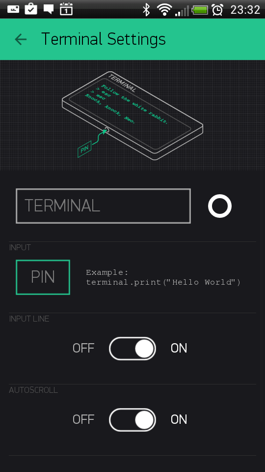
Displays data from your hardware. Allows to send any string to your hardware. Terminal always stores last 25 messages
your hardware had send to Blynk Cloud. This limit may be increased on Local Server with terminal.strings.pool.size
property.
You need to use special commands with this widget:
terminal.print();   // Print values, like Serial.print
terminal.println(); // Print values, like Serial.println()
terminal.write();   // Write a raw data buffer
terminal.flush();   // Ensure that data was sent out of device
terminal.clear();   // Erase all values in the terminal
Sketch: Terminal
Video Streaming
Simple widget that allows you to display any live stream. Widget supports RTSP (RP, SDP), HTTP/S progressive streaming, HTTP/S live streaming. For more info please follow official Android documentation.
At the moment Blynk doesn’t provide streaming servers. So you can either stream directly from camera, use 3-d party services or host streaming server on own server (on raspberry for example).
You can also change video url from hardware with:
Blynk.setProperty(V1, "url", "http://my_new_video_url");Level Display
Level Display is very similar to progress bar, when you need to visualize a level betwen min/max value To update Level Display from hardware side with code:
Blynk.virtualWrite(V1, val);Every message that hardware sends to server is stored automatically on server. PUSH mode doesn’t require application to be online or opened.
Sketch: Push Example
Notifications
Twitter widget connects your Twitter account to Blynk and allows you to send Tweets from your hardware.

Example code:
Blynk.tweet("Hey, Blynkers! My Arduino can tweet now!");Limitations:
- you cant’ send 2 tweets with same message (it’s Twitter policy)
- only 1 tweet per 5 seconds is allowed
Sketch: Twitter
Email widget allows you to send email from your hardware to any address.
Example code:
Blynk.email("my_email@example.com", "Subject", "Your message goes here");It also contains to field. With this field you may define receiver of email in the app.
You may skip to field when you want to send email to your Blynk app login email:
Blynk.email("Subject", "Your message goes here");You can send either text/html or text/plain (some clients don’t support text/html) email.
You can change this content type of email in the Mail widget settings.
Additionally you may use {DEVICE_NAME}, {DEVICE_OWNER_EMAIL} and {VENDOR_EMAIL} (for the local server)
placeholders in the mail for the to, subject and body fields:
Blynk.email("{DEVICE_OWNER_EMAIL}", "{DEVICE_NAME} : Alarm", "Your {DEVICE_NAME} has critical error!");
Limitations:
- Maximum allowed email + subject + message length is 120 symbols. However you can increase this limit if necessary
by adding
#define BLYNK_MAX_SENDBYTES XXXto you sketch. WhereXXXis desired max length of your email. For example for ESP you can set this to 1200 max length#define BLYNK_MAX_SENDBYTES 1200. The#define BLYNK_MAX_SENDBYTES 1200must be included before any of the Blynk includes. - Only 1 email per 5 seconds is allowed
- In case you are using gmail on the Local Server you are limited with 500 mails per day (by google). Other providers may have similar limitations, so please be careful.
- User is limited with 100 messages per day in the Blynk Cloud;
Sketch: Email
Push Notifications
Push Notification widget allows you to send push notification from your hardware to your device. Currently it also contains 2 additional options:
- Notify when hardware offline - you will get push notification in case your hardware went offline.
- Offline Ignore Period - defines how long hardware could be offline (after it went offline) before sending notification. In case period is exceeded - “hardware offline” notification will be send. You will get no notification in case hardware was reconnected within specified period.
- Priority high priority gives more chances that your message will be delivered without any delays. See detailed explanation here.
WARNING: high priority contributes more to battery drain compared to normal priority messages.
Example code:
Blynk.notify("Hey, Blynkers! My hardware can push now!");You can also use placeholder for device name, that will be replaced on the server with your device name:
Blynk.notify("Hey, Blynkers! My {DEVICE_NAME} can push now!");Limitations:
- Maximum allowed body length is 120 symbols;
- Every device can send only 1 notification every 5 seconds;
Sketch: PushNotification
Unicode in notify, email, push, …
The library handles all strings as UTF8 Unicode. If you’re facing problems, try to print your message to the Serial and see if it works (the terminal should be set to UTF-8 encoding). If it doesn’t work, probably you should read about unicode support of your compiler.
If it works, but your message is truncated - you need to increase message length limit (all Unicode symbols consume at least twice the size of Latin symbols).
Increasing message length limit
You can increase maximum message length by putting on the top of your sketch (before Blynk includes):
#define BLYNK_MAX_SENDBYTES 256 // Default is 128Interface
Tabs
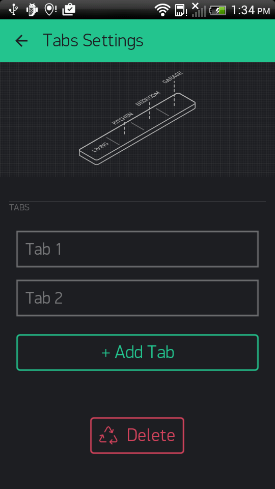
The only purpose of Tabs widget is to extend your project space. You can have up to 4 tabs. Also you can drag widgets between tabs. Just drag widget on the label of required tab of tabs widget.
Menu
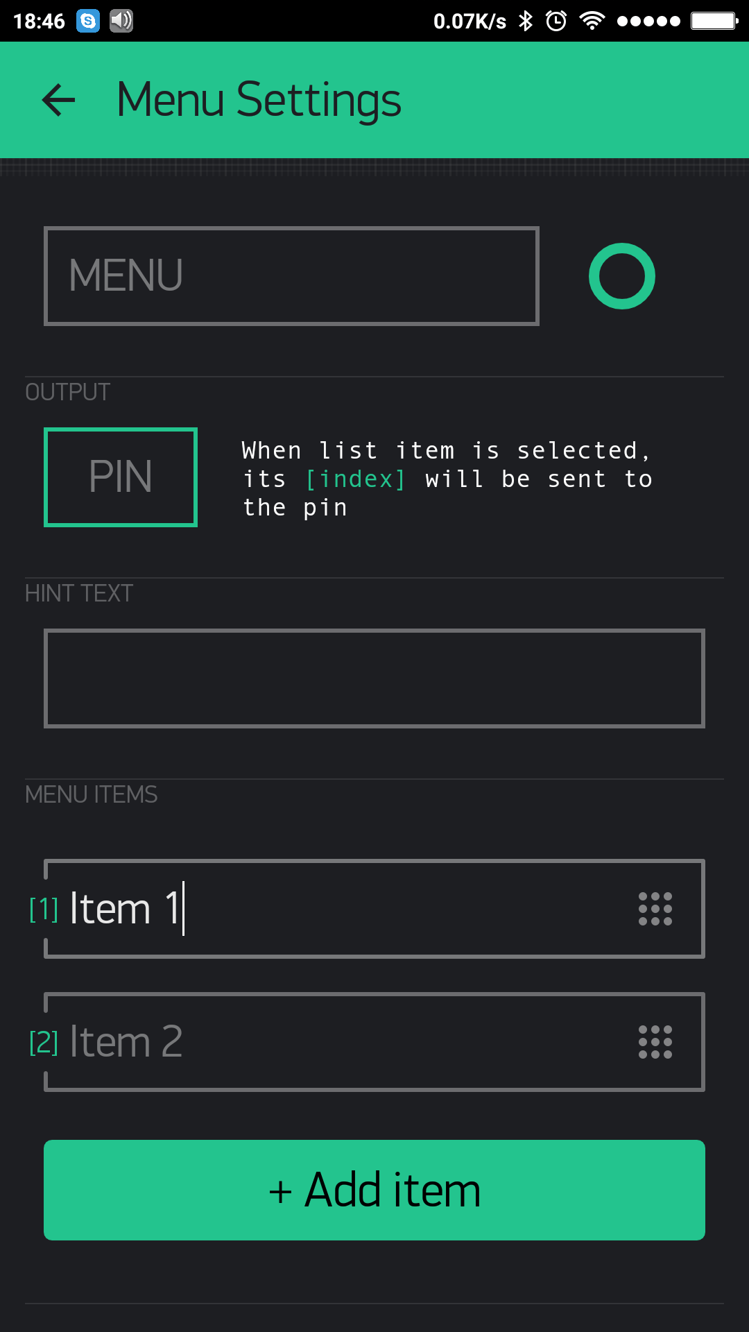
Menu widget allows you to send command to your hardware based on selection you made on UI. Menu sends index of element you selected and not label string. Sending index is starts from 1. It works same way as usual ComboBox element. You can also set Menu items from hardware side.
Example code:
switch (param.asInt())
  {
    case 1: { // Item 1
      Serial.println("Item 1 selected");
      break;
    }
    case 2: { // Item 2
      Serial.println("Item 2 selected");
      break;
    }
  }
Sketch: Menu
Time Input
Time input widget allows you to select start/stop time, day of week, timezone, sunrise/sunset formatted values
and send them to your hardware. Supported formats for time now are HH:MM and HH:MM AM/PM.
Hardware will get selected on UI time as seconds of day (3600 * hours + 60 * minutes) for start/stop time.
Time that widget sends to hardware is user local time.
Selected days indexes:
Monday - 1
Tuesday - 2
...
Saturday - 6
Sundays - 7
You can also change state of widget on UI. See below sketches.
Sketch: Simple Time Input for start time
Sketch: Advanced Time Input
Sketch: Update Time Input State on UI
Map
Map widget allows you set points/pins on map from hardware side. This is very useful widget in case you have multiple devices and you want track their values on map.
You can send a point to map with regular virtual wrtei command:
Blynk.virtualWrite(V1, pointIndex, lat, lon, "value");We also created wrapper for you to make suage of map simpler:
You can change button labels from hardware with:
WidgetMap myMap(V1);
...
int index = 1;
float lat = 51.5074;
float lon = 0.1278;
myMap.location(index, lat, lon, "value");
Using save index allows you to override existing point value.
Sketch: Basic Sketch
Table
Table widget comes handy when you need to structure similar data within 1 graphical element. It works as a usual table.
You can add a row to the table with:
Blynk.virtualWrite(V1, "add", id, "Name", "Value");You can update a row in the table with:
Blynk.virtualWrite(V1, "update", id, "UpdatedName", "UpdatedValue");To highlight any item in a table by using it’s id in a table:
Blynk.virtualWrite(V1, "pick", 0);To select/deselect (make icon green/grey) item in a table by using it’s row id in a table:
Blynk.virtualWrite(V1, "select", 0);
Blynk.virtualWrite(V1, "deselect", 0);
To clear the table at any time with:
Blynk.virtualWrite(V1, "clr");You can also handle other actions coming from table. For example, use row as a switch button.
BLYNK_WRITE(V1) {
   String cmd = param[0].asStr();
   if (cmd == "select") {
       //row in table was selected.
       int rowId = param[1].asInt();
   }
   if (cmd == "deselect") {
       //row in table was deselected.
       int rowId = param[1].asInt();
   }
   if (cmd == "order") {
       //rows in table where reodered
       int oldRowIndex = param[1].asInt();
       int newRowIndex = param[2].asInt();
   }
}
Note: Max number of rows in the table is 100. When you reach the limit, table will work as FIFO (First In First Out) list.
This limit can be changed by configuring table.rows.pool.size property for Local Server.
Sketch: Simple Table usage
Sketch: Advanced Table usage
Device Selector
Device selector is a powerful widget which allows you to update widgets based on one active device. This widget is particlularly helpful when you have a fleet of devices with similar functionality.
Imagine you have 4 devices and every device has a Temperature & Humidity sensor connected to it. To display the data for all 4 devices you would need to add 8 widgets.
With Device Selector, you can use only 2 Widgets which will display Temperature and Humidity based on the active device chosen in Device Selector.
All you have to do is:
- Add Device Selector Widget to the project
- Add 2 widgets (for example Value Display Widget) to show Temperature and Humidity
- In Widgets Settings you will be able assign them to Device Selector (Source or Target section)
- Exit settings, Run the project.
Now you can change the active device in Device Selector and you will see that Temperature and Humidity values are reflecting the data updates for the device you just picked.
NOTE: Webhook Widget will not work with Device Selector (yet).
Device Tiles
Device tiles is a powerful widget and very similar to the device selector widget, but with UI. It allows you to display 1 pin per device per tile. This widget is particularly helpful when you have a fleet of devices with similar functionality. So you can group similar devices within one layout (template).
Sensors
Accelerometer
Accelerometer is kind of motion sensors
that allows you to detect motion of your smartphone.
Useful for monitoring device movement, such as tilt, shake, rotation, or swing.
Conceptually, an acceleration sensor determines the acceleration that is applied to a device by measuring the forces
that are applied to the sensor. Measured in m/s^2 applied to x, y, z axis.
In order to accept data from it you need to:
BLYNK_WRITE(V1) {
  //acceleration force applied to axis x
  int x = param[0].asFloat();
  //acceleration force applied to axis y
  int y = param[1].asFloat();
  //acceleration force applied to axis y
  int z = param[2].asFloat();
}
Accelerometer doesn’t work in background.
Barometer/pressure
Barometer/pressure is kind of environment sensors that allows you to measure the ambient air pressure.
Measured in in hPa or mbar.
In oder to accept data from it you need to:
BLYNK_WRITE(V1) {
  //pressure in mbar
  int pressure = param[0].asInt();
}
Barometer doesn’t work in background.
Gravity
Gravity is kind of motion sensors that allows you to detect motion of your smartphone. Useful for monitoring device movement, such as tilt, shake, rotation, or swing.
The gravity sensor provides a three dimensional vector indicating the direction and magnitude of gravity.
Measured in m/s^2 of gravity force applied to x, y, z axis.
In oder to accept data from it you need to:
BLYNK_WRITE(V1) {
  //force of gravity applied to axis x
  int x = param[0].asFloat();
  //force of gravity applied to axis y
  int y = param[1].asFloat();
  //force of gravity applied to axis y
  int z = param[2].asFloat();
}
Gravity doesn’t work in background.
Humidity
Humidity is kind of environment sensors that allows you to measure ambient relative humidity.
Measured in % - actual relative humidity in percent.
In oder to accept data from it you need to:
BLYNK_WRITE(V1) {
  // humidity in %
  int humidity = param.asInt();
}
Humidity doesn’t work in background.
Light
Light is kind of environment sensors that allows you to measure level of light (measures the ambient light level (illumination) in lx). In phones it is used to control screen brightness.
In order to accept data from it you need to:
BLYNK_WRITE(V1) {
  //light value
  int lx = param.asInt();
}
Light doesn’t work in background.
Proximity
Proximity is kind of position sensors
that allows you to determine how close the face of a smartphone is to an object.
Measured in cm - distance from phone face to object. However most of this sensors returns only FAR / NEAR information.
So return value will be 0/1. Where 0/LOW is FAR and 1/HIGH is NEAR.
In order to accept data from it you need to:
BLYNK_WRITE(V1) {
  // distance to object
  int proximity = param.asInt();
  if (proximity) {
     //NEAR
  } else {
     //FAR
  }
}
Proximity doesn’t work in background.
Temperature
Temperature is kind of environment sensors
that allows you to measure ambient air temperature.
Measured in °C - celcius.
In order to accept data from it you need to:
BLYNK_WRITE(V1) {
  // temperature in celcius
  int celcius = param.asInt();
}
Temperature doesn’t work in background.
GPS Trigger
GPS trigger widget allows easily trigger events when you arrive to or leave from some destination. This widget
will work in background and periodically will check your coordinates. In case your location is within/out required
radius (selected on widget map) widget will send HIGH/LOW command to hardware. For example, let’s assume you have
GPS Trigger widget assigned to pin V1 and option Trigger When Enter. In that case when you’ll arrive to destination
point widget will trigger HIGH event.
BLYNK_WRITE(V1) {
  int state = param.asInt();
  if (state) {
      //You enter destination
  } else {
      //You leave destination
  }
}
More details on how GPS widget works you can read here.
GPS trigger widget works in background.
GPS Streaming
Useful for monitoring smartphone location data such as latitude, longitude, altitude and speed (speed could be often 0
in case smartphone doesn’t support it).
In order to accept data from this widget you need to:
BLYNK_WRITE(V1) {
  float latitude = param[0].asFloat();
  float longitude = param[1].asFloat();
  float altitude = param[2].asFloat();
  float speed = param[3].asFloat();
}
or you can use prepared wrapper GpsParam:
BLYNK_WRITE(V1) {
  GpsParam gps(param);
  // Print 6 decimal places for Lat
  Serial.println(gps.getLat(), 7);
  Serial.println(gps.getLon(), 7);

  Serial.println(gps.getAltitude(), 2);
  Serial.println(gps.getSpeed(), 2);
}
GPS Streaming works in background.
Sketch: GPS Stream
Other
Bridge
Bridge can be used for Device-to-Device communication (no app. involved). You can send digital/analog/virtual write commands from one device to another, knowing it’s auth token.
At the moment Bridge widget is not required on application side (it is mostly used for indication that we have such feature).
You can use multiple bridges to control multiple devices.

Bridge widget takes a virtual pin, and turns it into a channel to control another device. It means you can control any virtual, digital or analog pins of the target device.
Be careful not to use pins like A0, A1, A2 ... when communicating between different device types, as Arduino Core may refer to wrong pins in such cases.
Example code for device A which will send values to device B:
WidgetBridge bridge1(V1); //Initiating Bridge Widget on V1 of Device A
...
void setup() {
    Blynk.begin(...);
    while (Blynk.connect() == false) {
        // Wait until Blynk is connected
    }
    bridge1.digitalWrite(9, HIGH); // will trigger D9 HIGH on Device B. No code on Device B required
    bridge1.analogWrite(10, 123);
    bridge1.virtualWrite(V1, "hello"); // you need to write code on Device B in order to receive this value. See below
    bridge1.virtualWrite(V2, "value1", "value2", "value3");
}

BLYNK_CONNECTED() {
  bridge1.setAuthToken("OtherAuthToken"); // Token of the hardware B
}
IMPORTANT: when performing virtualWrite() with Bridge Widget, Device B would need to process the incoming data from Device A.
For example, if you are sending value from Device A to Device B using bridge.virtualWrite(V5) you would need to use this handler on Device B:
BLYNK_WRITE(V5){
    int pinData = param.asInt(); //pinData variable will store value that came via Bridge
}
Keep in mind that bridge.virtualWrite doesn’t send any value to mobile app. You need to call Blynk.virtualWrite for that.
Sketch: Bridge
Eventor
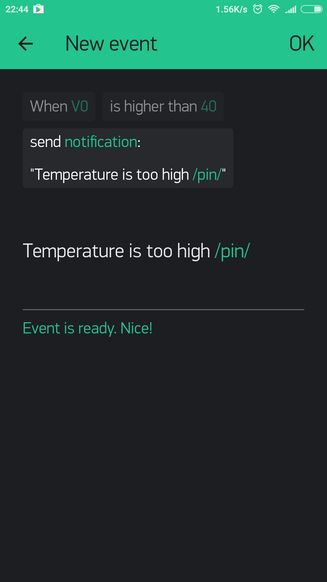
Eventor widget allows you to create simple behaviour rules or events. Let’s look at a typical use case: read temperature from DHT sensor and send push notification when the temperature is over a certain limit:
  float t = dht.readTemperature();
  if (isnan(t)) {
    return;
  }
  if (t > 40) {
    Blynk.notify(String("Temperature is too high: ") + t);
  }
With Eventor you don’t need to write this code. All you need is to send the value from the sensor to the server:
  float t = dht.readTemperature();
  Blynk.virtualWrite(V0, t);
Don’t forget that virtualWrite commands should be wrapped in the timer and can’t be used in the main loop.
Now configure new Event in Eventor widget:
NOTE Don’t forget to add notification widget.
Eventor comes handy when you need to change conditions on the fly without re-uploading new sketch on
the hardware. You can create as many events as you need.
Eventor also could be triggered from the application side.
You just need to assign the widget to the same pin as your Event within Eventor.
Eventor doesn’t constantly sends events. Let’s consider simple event as above if (temperature > 40) send notification.
When temperature goes beyond 40 threshold - notification action is triggered. If temperature continues to stay above the
40 threshold no actions will be triggered. But if temperature goes below threshold and then passes it again -
notification will be sent again (there is no 5 sec limit on Eventor notifications).
Eventor also supports Timer events. For example, you can set a pin V1 ON/HIGH at 21:00:00 every Friday.
With Eventor Time Event you can assign multiple timers on same pin, send any string/number, select days and timezone.
In order to remove created event please use swipe. You can also swipe out last element in the Event itself.
NOTE: The timer widget rely on the server time and not your phone time. Sometimes the phone time may not match the server time. NOTE: Events are triggered only once when the condition is met. That’s mean chaining of events is not possible (however, could be enabled for commercials).
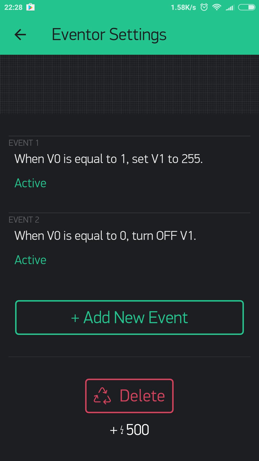
Sketch: Eventor
NOTE:: Events are triggered only once when the condition is met.
Exception:
Let’s consider simple event as above if (temperature > 40) send notification.
When temperature goes beyond 40 threshold - notification action is triggered. If temperature continues to stay above the 40 threshold no actions will be triggered. But if temperature goes below threshold and then passes it again -
notification will be sent again (there is no 5 sec limit on Eventor notifications).
RTC
Real-time clock allows you to get time from server. You can preselect any timezone on UI to get time on hardware in required locale. No pin required for RTC widget.
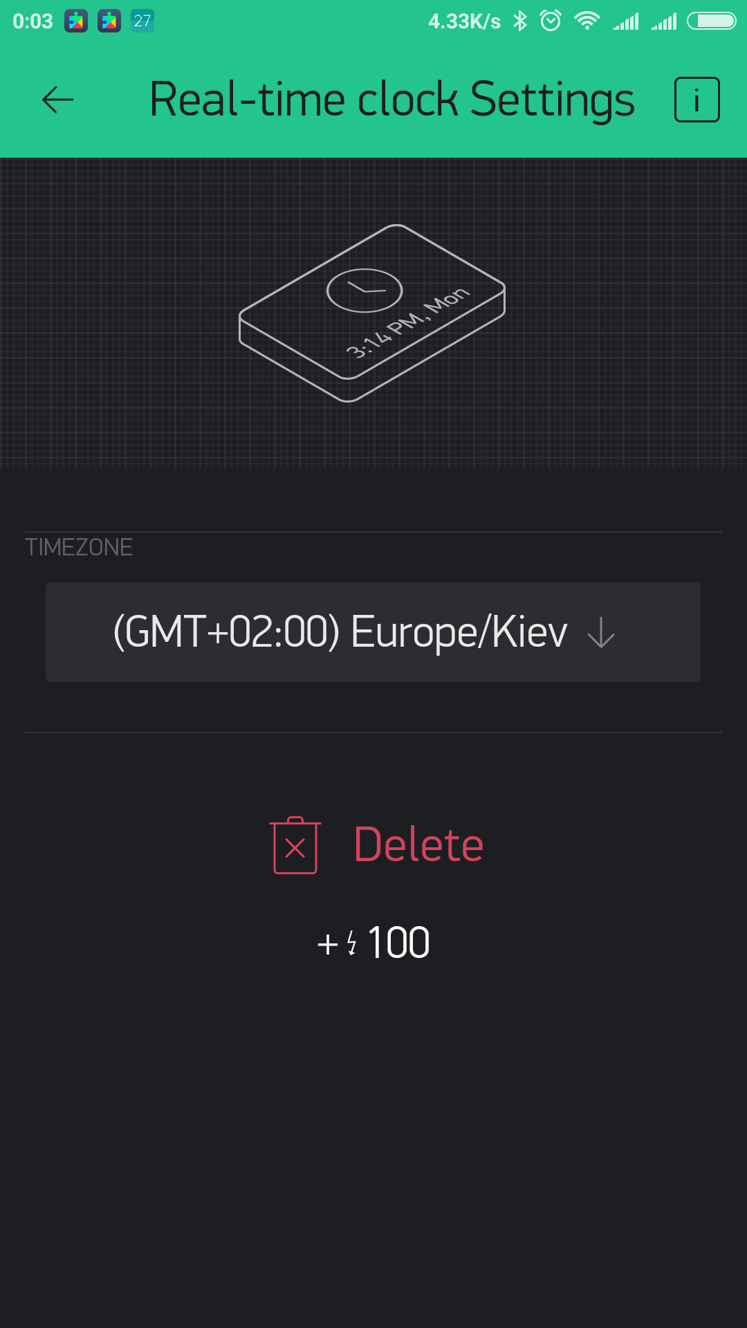
Sketch: RTC
BLE
Widget to enable Bluetooth Low Energy support. At the moment BLE widget requires internet connection in order to login and load your profile. However this will be fixed soon. Also some Blynk widgets are not supported within the BLE connection.
Blynk currently supports a handful of different BLE modules. Please check sketches below.
Sketches: BLE
Bluetooth
Widget to enable Bluetooth support. At the moment Bluetooth widget is supported only on Android and requires internet connection to login and to load your profile. This will be fixed soon. Alsom some Blynk widgets do not work within the Bluetooth connection.
Blynk currently supports bunch of different modules. Please check sketches below.
Sketches: Bluetooth
Music Player
Simple UI element with 3 buttons with common music player controls. Every button sends it’s own command to hardware:
play, stop, prev, next.
You can change widget state within the app from hardware side with next commands:
Blynk.virtualWrite(Vx, “play”);
Blynk.virtualWrite(Vx, “stop”);
You can also change widget play/stop state with next code (equivalent to above commands):
Blynk.setProperty(V1, "isOnPlay", "false");
Sketch: Music Player
Webhook
Webhook is a widget designed to communicate with 3rd party services. With Webhook widget you can send HTTP(S) requests to any 3rd party service or device that has HTTP(S) API (e.g. Philips Hue bulb). You can trigger 3-d party service with a single click of a button.
Any write operation from hardware side will trigger Webhook Widget. You can also trigger webhook from Blynk app when a app widget is assigned to the same pin as Webhook.
For example, when you need to send data from your hardware not only to Blynk, but also to Thingspeak, you would need to write a long http request code like this (this is just an example, not a full sketch):
WiFiClient client;
if (client.connect("api.thingspeak.com", 80)) {
    client.print("POST /update HTTP/1.1\n");
    client.print("Host: api.thingspeak.com\n");
    client.print("Connection: close\n");
    client.print("X-THINGSPEAKAPIKEY: " + apiKeyThingspeak1 + "\n");
    client.print("Content-Type: application/x-www-form-urlencoded\n");
    client.print("Content-Length: ");
    client.print(postStr.length());
    client.print("\n\n");
    client.print(postStr);
}
Instead, with Webhook widget you would only need to fill in these fields:
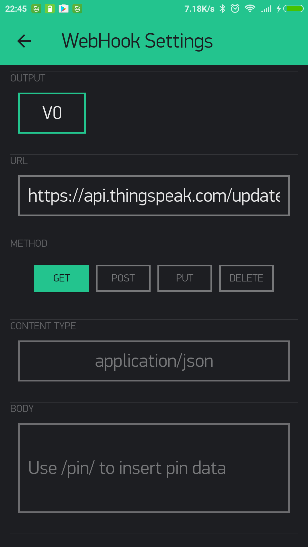
And add this code on hardware side:
Blynk.virtualWrite(V0, value);where V0 is pin assigned to the Webhook widget.
Use standard Blynk placeholders for Pin Value in the body or URL, for example:
https://api.thingspeak.com/update?api_key=xxxxxx&field1=/pin/or for the body
["/pin/"]When you need to send an array of values, you can refer to a specific index of the array value. Blynk Pin can hold an array of max 10 values:
/pin[0]/,/pin[1]/, /pin[2]/
You can also make GET requests from Blynk Server and get responses directly to your hardware.
For example, to get current weather from a 3rd party Weather service that uses an URL similar to this:
http://api.sunrise-sunset.org/json?lat=33.3823&lng=35.1856&date=2016-10-01, you would need to put this URL in Webhook widget and assign it to V0 pin.
To parse the response on the hardware side:
BLYNK_WRITE(V0){
  String webhookdata = param.asStr();
  Serial.println(webhookdata);
}
Now, every time there is a “write” command to V0 pin (e.g. with Blynk.virtualWrite(V0, 1) from hardware or from app widget assigned to V0), BLYNK_WRITE(V0) construction will be triggered and processed.
NOTE: Usually, 3rd party servers return long responses. You have to increase the maximum allowed message size your hardware can process. Modify this line in your firmware code:
#define BLYNK_MAX_READBYTES 1024. Where 1024 - is maximum allowed message size.
NOTE: Blynk Cloud has limitation for Webhook Widget - you can only send 1 request per second. This can be
changed on a Local Server by changing webhooks.frequency.user.quota.limit. Be careful with Webhooks,
as many 3rd party services can’t handle 1 req/sec, and you can be banned on some of them.
For example, Thingspeak allows only 1 request per 15 seconds.
NOTE: To avoid spamming, Blynk Webhook feature has another limitation - if your Webhook requests fail 10 times in a row, Webhook Widget will be stopped. To resume it, you would need to open Widget Settings and re-save it. Failed request is a request that doesn’t return 200 or 302.
NOTE: Webhook widget may affect Blynk.syncAll() function when a returned response is large.
Reports Widget
Function of Reports is to configure and customize data reports in CSV format. You can choose between one-time or continuous scheduled reports.
Also, within the Reports you can clear all the data collected by your devices.
You need to configure initial inputs in Edit mode, and then, in Play mode you will be able to customize reports.
Edit mode. Data inputs configuration
In edit mode (when your project is stopped) you define the Datastreams you would like to later be included in reports. Reports widget is designed to work with the Device Tiles widget. If you don’t use Device Tiles you can still select a single device or a group of devices as a source of data for reports.
You have to choose either Device Tiles or single / group of the devices for the report. You can’t combine these 2 options.
Play mode.
After you added source devices and their Datastreams click Play button and click on the Reports button.
Customizing Reports.
Every Report option supposes it’s own settings:
Report name - give your report a meaningful name.
Data source - select the Datastreams you would like to be included in reports.
Report Frequency - Defines how often reports will be sent. They can be one-time and scheduled.
one-time - will instantly generate report and send it to the email addresses specified. Click on the right icon to send it.
Scheduled reports can be sent daily/weekly/monthly.
At Time will set up a time of the day the report will be sent.
Start/End specifies start and end date the reports will continue to be sent.
For Weekly Report you can select a day of the week when report should be sent. For Monthly report you can choose whether to send report on the first or last day of the month.
Recipients - specify up to 5 email addresses.
Data resolution defines granularity of your reports. Supported granularities are: minute, hourly and daily.
For example, when you generate daily report with 1 minute granularity you’ll get 24 * 60 * 60
points in your daily report for every selected Datastream.
Group data in reports by - specify the output format of the CSV file(s).
Datastream you will get 1 CSV file for each Datastream.
Device you will get 1 CSV file per each device. Each file will contain all of the included Datastreams.
Report you will get 1 CSV file for all your devices and all your Datastreams.
Timezone correction - specify the time zone adjustment if you need to get report date and time adjusted to a specific time zone
Date and time format - defines the format of the timestamp field of your data. You can select 2018-06-21 20:16:48,
2018-06-21T20:16:48+03:00 or other supported formats.
There is one specific Timestamp format - which reflects the difference between the current time and midnight, January 1, 1970 UTC measured in milliseconds.
After the report is set up - click on “OK” button at the right upper corner. Your report is ready.
Once you configured the report you will see when is the Next report scheduled and also a schedule for this report.
After the report was sent at least once, you can see when the Last report was sent.
Last label also contains the status regarding the report:
OK: the report was generated and sent to the Recipients successfully;No Data: the report doesn’t contain any data for the configured period;Error: something went wrong. Please contact the Blynk Team support;
Reports will be generated even if your project is not in active (Play) mode. However, inactive projects don’t generate any data.
NOTE: all reports are encoded in UTF-16. Please, make sure you selected UTF-16 as required “Character set” for your csv reader.
Sharing
Blynk offers two types of sharing your projects with other people:
Share access to your hardware. Think about giving someone an App for your Project. They can’t modify, but can control and see what’s there.
Share your Project configuration. Others will get a clone of your project by scanning a given QR link, but they won’t be able to control your hardware. It’s great for tutorials, instructables, etc.
Shared access to your hardware
Imagine giving someone an App to control your Project.
- people you’ve shared your project with can’t modify anything. They can only use it
- you can update your app, change the layout, add widgets and it’s immediately synced to everyone
- you can revoke access at any moment
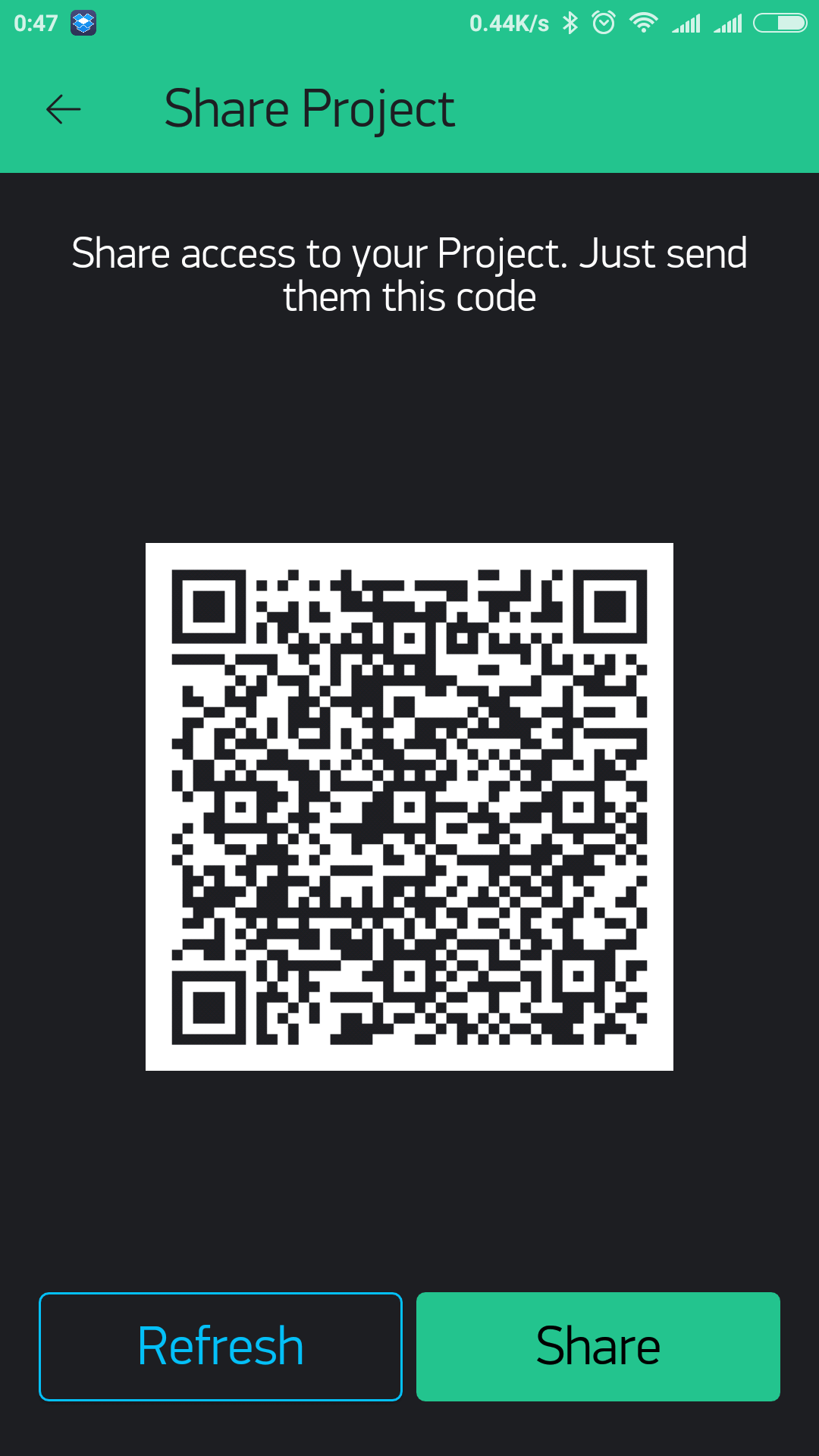
How it works: - you send the QR code to your users (you can email, print, post to social media, do whatever you want) - others download Blynk app, scan the QR code and your app opens for them ready to use. They don’t even need to login or create an account.
Go to your Project’s Settings:
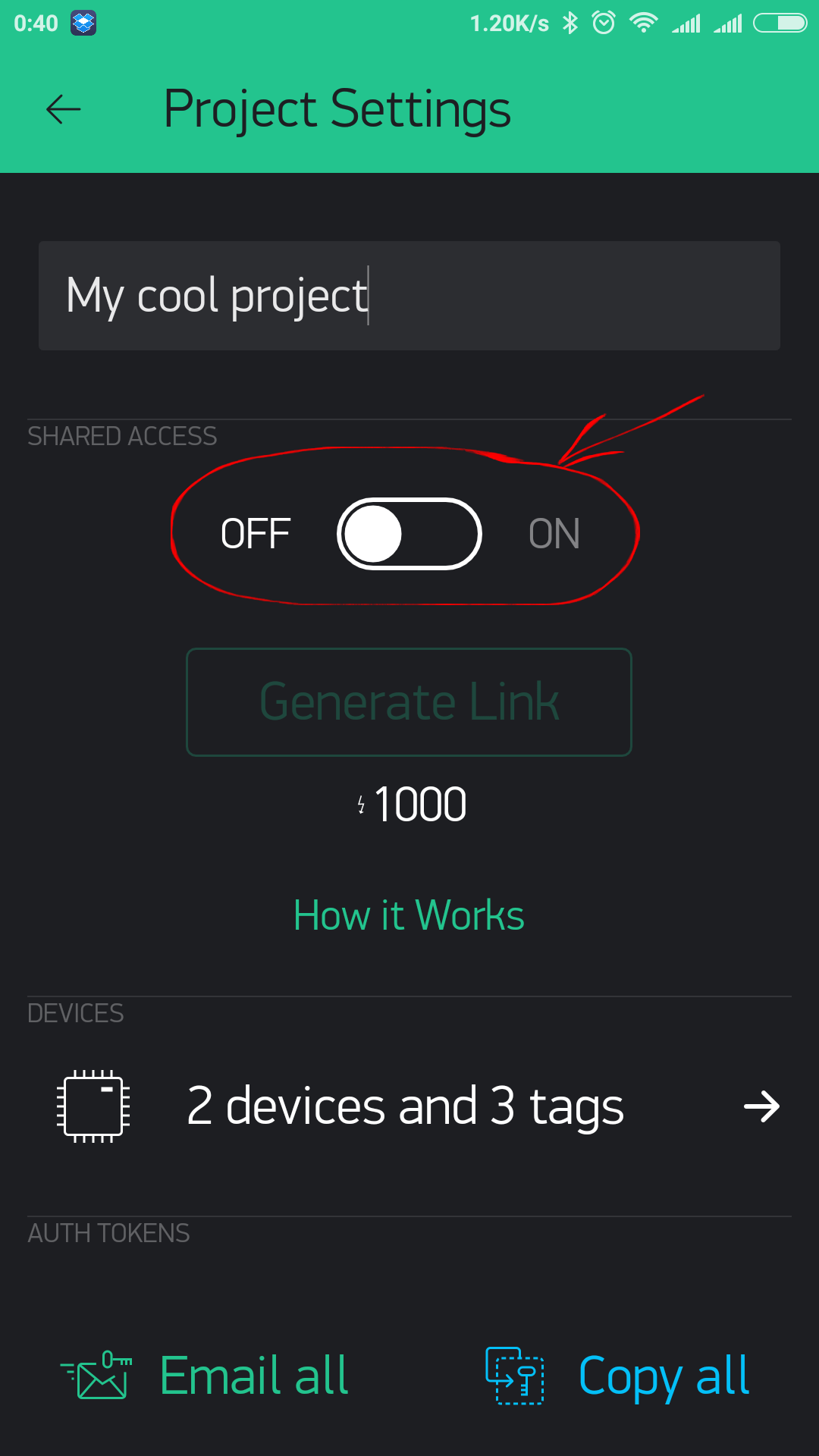
Click on “Generate Link” button :
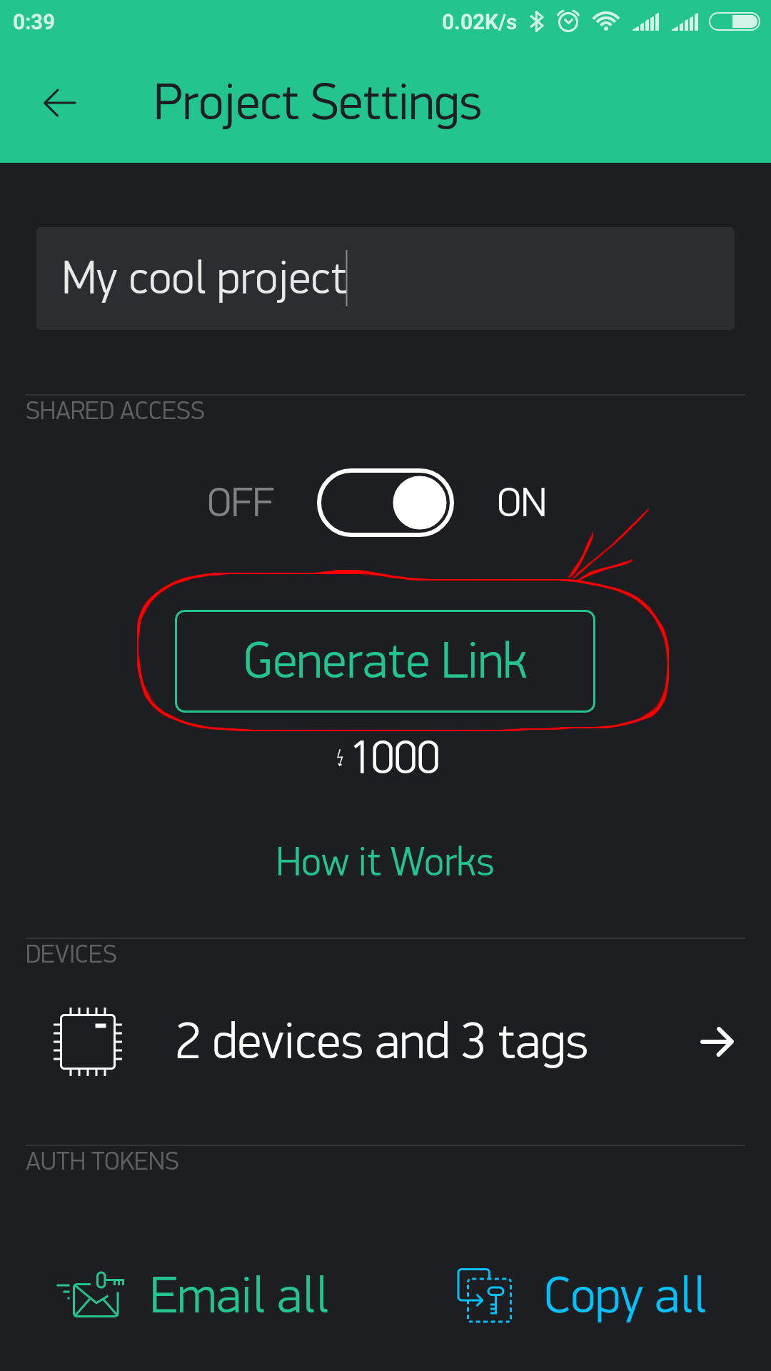
It will generate QR code you can share with others:
That’s it! Now Exit the settings and press PLAY button.
Another person would need to install Blynk app and scan QR code from the login screen (scanning from existing profile is not yet supported) ;
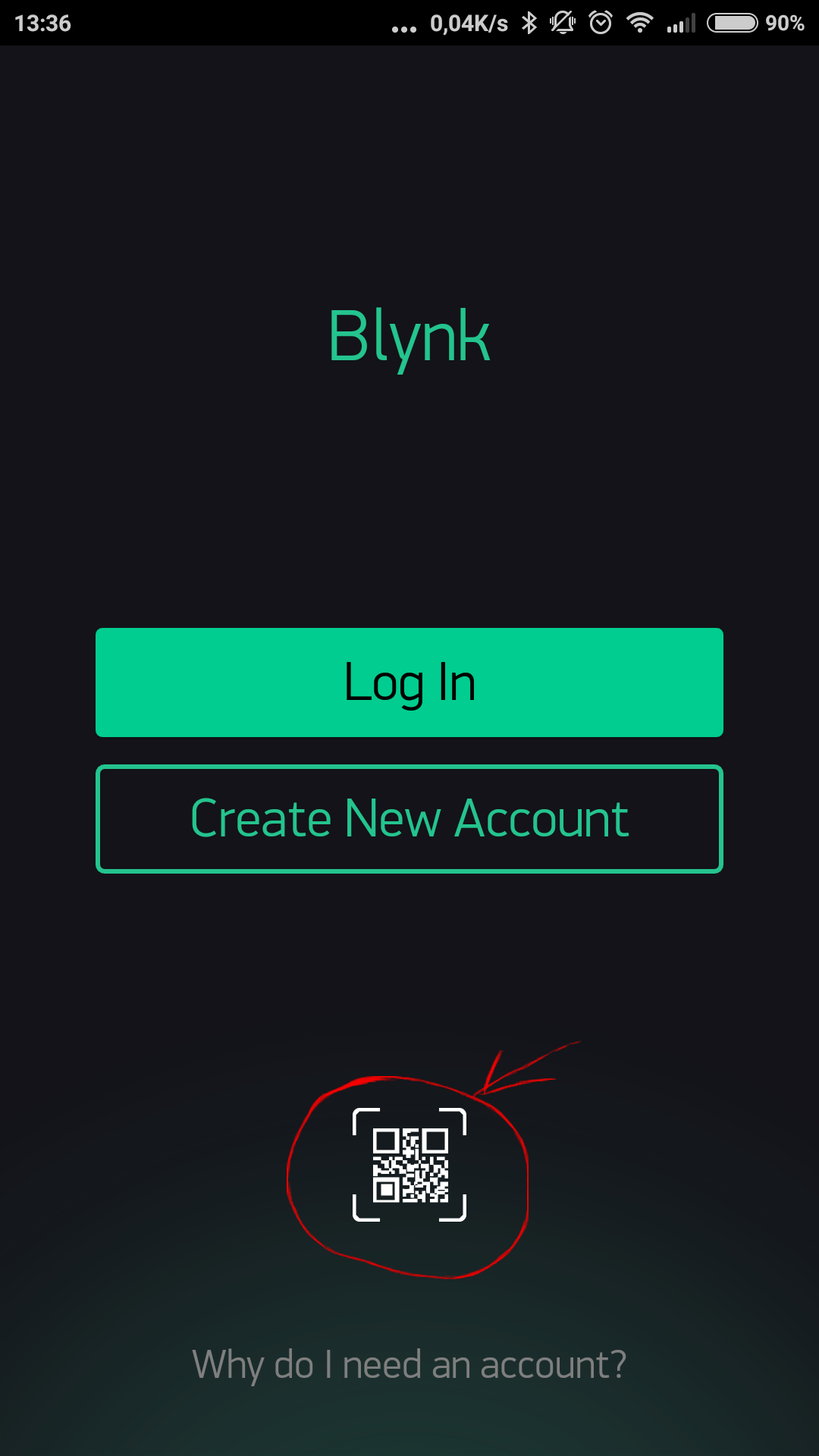
NOTE: Your Project should be active, don’t forget to press Play button.
WARNING: Sharing costs 1000 energy and this energy is not recoverable even you didn’t use sharing at all.
Share your Project configuration
In case you want to share your Project’s set up without giving access to your hardware (for example to make a tutorial or instructable)- follow the steps:
In Project’s Settings go to Clone button.
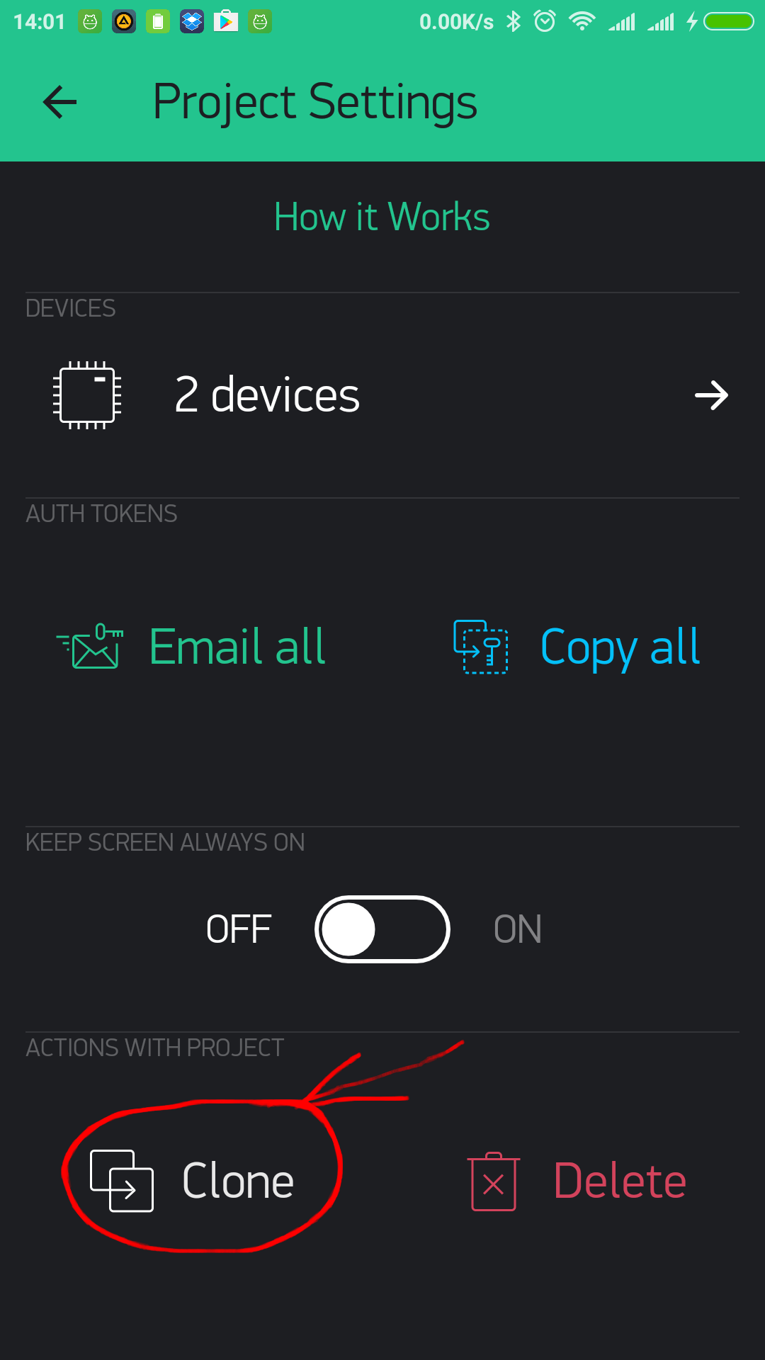
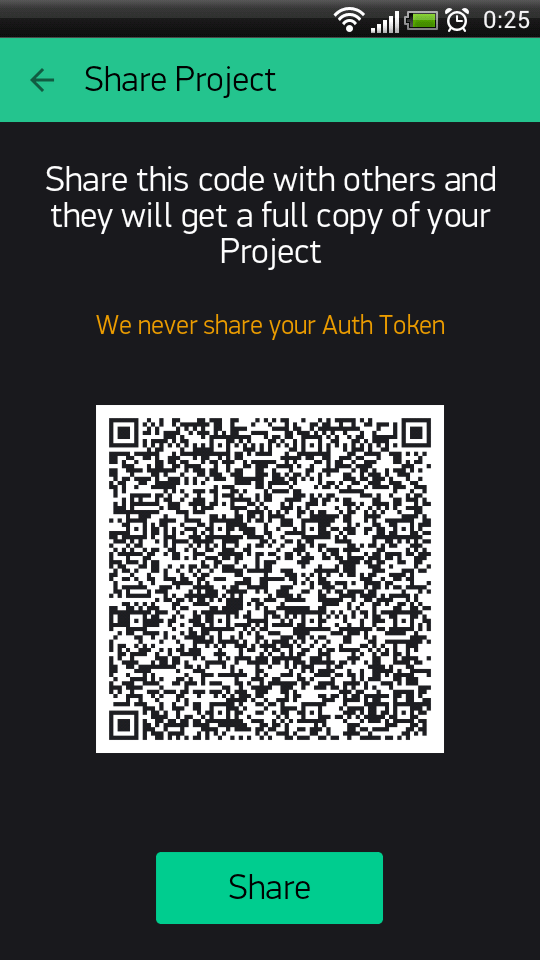
It will generate QR code you can share with anyone.
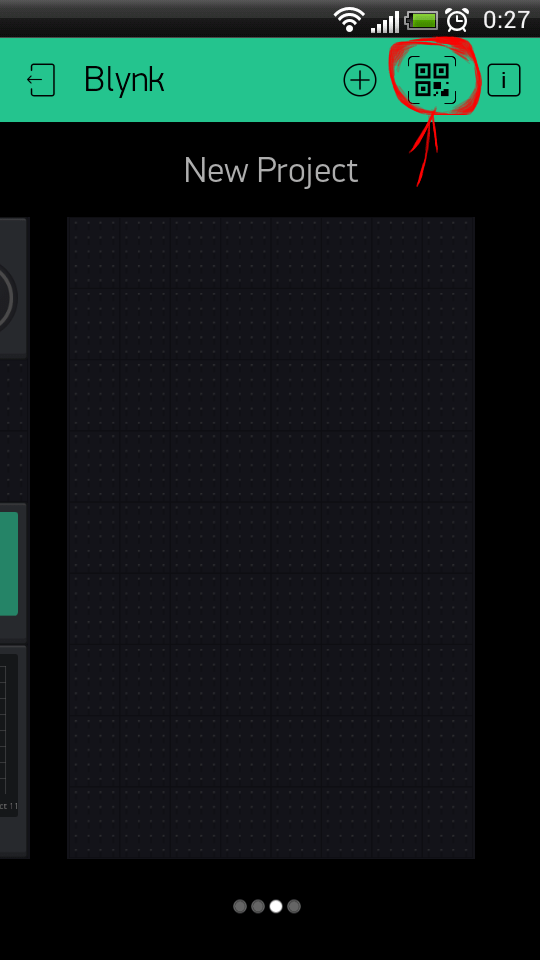
Another person should Log In to Blynk app and press QR button in Projects gallery
After the scan, a new Project will be created, all the widgets, settings, layout will be cloned. Another person would need enough Energy Balance to clone your Project.
Auth Token will be different!. Nobody will get access to your hardware. They just get a copy of the layout and settings.
HTTP RESTful API
Blynk HTTP RESTful API allows to easily read and write values of Pins in Blynk apps and Hardware.
API description can be found here. Warning: Blynk HTTP API still has GEO DNS issue. This means, for now you need to use direct server IP instead of hostname in order to make it work with 3-d party services like IFTTT.
Supported Hardware
Blynk supports more than 400 boards already, including support for Arduino, Particle, ARM mbed, TI Energia, MicroPython, Node.js, OpenWRT and many Single Board Computers. You can add your own connection types easily (see these examples for Arduino)!
Platforms
Arduino (https://github.com/diyeverythingvn/blynk-library-legacy)
- Arduino MKR WiFi 1010
- Arduino MKR GSM 1400
- Arduino MKR NB 1500
- Arduino Uno, Duemilanove
- Arduino Nano, Mini, Pro Mini, Pro Micro, Due, Mega
- Arduino 101 (Intel Curie, with BLE)
- Arduino MKR1000
- Arduino Zero
- Arduino Yún (onboard WiFi and Ethernet, via Bridge)
- Arduino.org UNO WiFi
- Arduino MKR VIDOR 4000 (use the example for MKR WiFi 1010)
- Arduino UNO WiFi Rev.2 (use the example for MKR WiFi 1010)
Arduino-like
- Blynk Board
- ESP8266 (Generic, NodeMCU, Witty Cloud, Huzzah, WeMos D1, Seeed Wio Link, etc.)
- ESP32 (WiFi, BLE)
- Nordic nRF51/nRF52 - based boards
- Teensy 3.2/3.1
- Blue Pill (STM32F103C)
- Realtek RTL8710 / Ameba via RTLduino
- BBC micro:bit
- LightBlue Bean , soon
- DFRobot Bluno
- RedBear Duo (WiFi, BLE)
- RedBearLab Blend Micro
- RedBearLab BLE Nano (v1 and v2)
- Seeed Tiny BLE
- Simblee BLE
- RFduino BLE
- The AirBoard (BLE-Link, RN-XV)
- Feather M0 WiFi
- Feather 32u4 BLE
- Intel Edison
- Intel Galileo
- Fishino Guppy, Uno, Mega
- TinyCircuits TinyDuino (CC3000)
- Microduino/mCookie Core, Core+, CoreUSB
- Wicked WildFire V2, V3, V4
- Digistump Oak
- chipKIT Uno32
- Alorium XLR8 (FPGA)
- LinkIt ONE (WiFi only)
Energia
- Texas Instruments
- CC3220SF-LaunchXL
- CC3200-LaunchXL
- Tiva C Connected LaunchPad
- Stellaris LM4F120 LaunchPad
- MSP430F5529 + CC3100
- LaunchPad MSP432
- RedBearLab (CC3200, WiFi Mini)
- Texas Instruments
Particle https://github.com/vshymanskyy/blynk-library-spark)
- Core
- Photon
- Electron
- RPi
- SparkFun RedBoard
- RedBear Duo (WiFi & BLE)
ARM mbed (https://developer.mbed.org/users/vshymanskyy/code/Blynk/)
- Seeed Tiny BLE
- RedBearLab BLE Nano
- BBC micro:bit
- STM32 Nucleo + Wiznet 5100 , soon
JavaScript (Node.js, Espruino, Browsers) (https://www.npmjs.com/package/blynk-library)
- Regular PC with Linux / Windows / OS X
- Raspberry Pi (Banana Pi, Orange Pi, …)
- BeagleBone Black
- Onion Omega
- Onion Omega 2
- Intel Galileo
- Intel Edison
- Intel Joule
- LeMaker Guitar
- LeMaker Banana Pro
- Samsung ARTIK 5
- PandaBoard, CubieBoard, pcDuino, Tessel 2
- VoCore, VoCore2 (OpenWRT + Espruino package)
- Espruino Pico
- …
Python (https://github.com/vshymanskyy/blynk-library-python)
- MicroPython
- Python 2
- Python 3
Lua (https://github.com/blezek/blynk-esp)
- NodeMCU
Arduino connection types
USB (Serial), connected to your laptop or desktop
Ethernet
- Arduino MKR ETH
- Arduino Ethernet Shield (W5100)
- Arduino Ethernet Shield 2 (W5500)
- SeeedStudio Ethernet Shield V2.0 (W5200)
- ENC28J60-based modules
WiFi
- ESP8266 as WiFi modem (running original firmware)
- Arduino WiFi 101 Shield
- Arduino WiFi Shield
- WIZnet WizFi310
- Adafruit CC3000 WiFi Breakout / Shield
- RN-XV WiFly
Bluetooth Smart (BLE 4.0)
- HM-10, HC-08
- DFRobot BLE-Link module
- Microduino/mCookie BLE
- RedBearLab BLE Mini
- nRF8001-based boards (Adafruit Bluefruit LE, etc.)
Bluetooth 2.0 Serial Port Profile (SPP)
- HC-05, HC-06, …
Cellular (GSM/3G/LTE)
- SIMCom SIM800 series (SIM800A, SIM800C, SIM800L, SIM800H, SIM808, SIM868)
- SIMCom SIM900 series (SIM900A, SIM900D, SIM908, SIM968)
- A6/A7
- M590
- BG96
- GPRSbee
- Microduino GSM
- Adafruit FONA (Mini Cellular GSM Breakout)
- Adafruit FONA 800/808 Shield
Made by Community
- Marvell® EZ-Connect™ MW300/MW302
- WIZnet-W5500-EVB
- LabVIEW
- Node-RED (can be used as bridge to HTTP, TCP, UDP, MQTT, XMPP, IRC, OSC…)
Problematic Boards
These boards are not supported and do not work out of the box: - Arduino Tian
Here is a list of known library issues
Troubleshooting
Connection
If you experience connection problems, follow these steps:
- Check that your hardware, wires, cables and power supply are good quality, not harmed or damaged, etc.
Use high power USB cables and USB ports. - Check your wiring using the examples (TCP/HTTP Client or similar) provided with your shield and hardware.
- Once you understand how to manage connection, it’s much easier to use Blynk.
- Try running command
telnet blynk-cloud.com 80from your PC, connected to the same network as your hardware. You should see something like:Connected to blynk-cloud.com.. - Try running Blynk default examples for your platform without modifications to see if it is working.
- Double-check that you have selected the right example for your connection type and hardware model.
- Our examples come with comments and explanations. Read them carefully.
- Check that your Auth Token is valid (copied from the App and doesn’t contain spaces, etc.)
- If it doesn’t work, try looking into serial debug prints.
- Done! Add your modifications and functionality. Enjoy Blynk!
Note: when you have multiple devices connected to your network, they should all have different MAC and IP addresses. For example, when using 2 Arduino UNO with Ethernet shields, flashing default example to both of them will cause connection problems. You should use manual ethernet configuration example.
WiFi network connection
If you encounter WiFi connection problems, please check these pitfalls:
- You’re trying to connect to “WPA & WPA2 Enterprise” network (often used in offices), and your shield does not support this security method
- Your WiFi network has a login page that requests entering an access token (often used in restaurants)
- Your WiFi network security disallows connecting alien devices completely (MAC filtering, etc)
- There is a firewall running. Default port for hardware connections is 80 (8080 on the Local Server). Make sure it’s open.
Delay
If you use long delay() or send your hardware to sleep inside of the loop() expect connection drops and downgraded performance.
DON’T DO THAT:
void loop()
{
  ...
  delay(1000); // this is long delay, that should be avoided
  other_long_operation();
  ...
  Blynk.run();
}
Note: This also applies to the BLYNK_READ & BLYNK_WRITE handlers!
SOLUTION: If you need to perform actions in time intervals - use timers, for example BlynkTimer.
Flood Error
If your code frequently sends a lot of requests to our server, your hardware will be disconnected. Blynk App may show “Your hardware is offline”
When Blynk.virtualWrite is in the void loop, it generates hundreds of “writes” per second
Here is an example of what may cause flood. DON’T DO THAT:
void loop()
{
  Blynk.virtualWrite(1, value); // This line sends hundreds of messages to Blynk server
  Blynk.run();
}
SOLUTION: If you need to perform actions in time intervals - use timers, for example BlynkTimer.
Using delay() will not solve the problem either. It may cause another issue. Use timers!
If sending hundreds of requests is what you need for your product you may increase flood limit on local server
and within Blynk library.
For local server you need to change user.message.quota.limit property within server.properties file :
    #100 Req/sec rate limit per user.
    user.message.quota.limit=100
For library you need to change BLYNK_MSG_LIMIT property within BlynkConfig.h file :
    //Limit the amount of outgoing commands.
    #define BLYNK_MSG_LIMIT 20
Enable debug
To enable debug prints on the default Serial, add this on the top of your sketch (it should be the first line in your sketch):
#define BLYNK_DEBUG // Optional, this enables lots of prints
#define BLYNK_PRINT Serial
And enable serial in void setup():
Serial.begin(9600);You can also use spare Hardware serial ports or SoftwareSerial for debug output (you will need an adapter to connect to it with your PC).
Note: enabling debug mode will slow down your hardware processing speed up to 10 times.
Geo DNS problem
Geo DNS issue is no longer a problem. It was solved in 2017.
Reset password
On login screen click on “Forgot password?” label and than type your email and Send button.
You’ll get instruction on your email.
Android reset password flow
- Open instruction email from your smartphone or tablet;
- Click on “Reset now” button in your email;
- Click on Blynk icon in below popup and reset the pass:
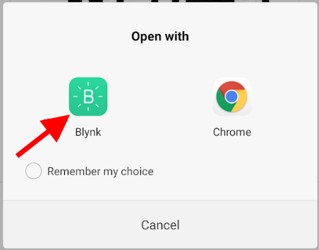
Security
Blynk server has 5 ports open for different security levels.
- 80 - plain TCP connection for the hardware (no security)
- 8080 - plain TCP connection for hardware (no security)
- 443 - SSL/TLS connection for the Mobile Apps and hardware with SSL
- 9443 - SSL/TLS connection for the Mobile Apps and hardware with SSL
Hardware may select to connect to 443 (9443) or 80 (8080), depending on it’s capabilities. Connection between the app and the server is always is done through SSL/TLS, so it is always secured. Connection between the hardware and server depends on your hardware capabilities.
Use Local Blynk Server
Local Blynk Server is no longer supported.
Use SSL gateway
Most platforms are not capable to handle SSL, so they connect to 80. However, our gateway script can be used to add SSL security layer to communication.
./blynk-ser.sh -f SSLThis will forward all hardware connections from 9443 port to the server via SSL gateway. You can run this script on your Raspberry Pi, desktop computer, or even directly on your router!
Note: when using your own server, you should overwrite the bundled server.crt certificate, or specify it to the script using --cert switch:
./blynk-ser.sh -f SSL -s <server ip> -p 9443 --cert=<certificate>.crtFlag -f SSL is enabled by default for USB communication so you don’t have to explicit declare it.
Note: SSL is supported by the gateway only on Linux/OSX for now
If you want to skip SSL, and connect to TCP, you can also do that:
./blynk-ser.sh -t TCPOTA
Blynk also supports over the air updates for - ESP8266, NodeMCU and SparkFun Blynk boards. OTA supported only for the private servers and for the paid customers for now.
How does it work?
- You need to use regular sketch for exported apps;
- After you launched your hardware you are ready for OTA;
- You can trigger the firmware update for the specific hardware via it’s token or for all hardware.
Flow
- User triggers OTA with one of below HTTPS request;
- User provides within HTTPS request admin credentials and firmware binary file to update hardware with;
- When hardware connects to server - server checks it firmware. In case, hardware firmware build date differs from uploaded firmware, than server sends special command to hardware with url for the new firmware;
Hardware processes url with below handler:
BLYNK_WRITE(InternalPinOTA) { //url to get firmware from. This is HTTP url //http://localhost:8080/static/ota/FUp_2441873656843727242_upload.bin overTheAirURL = param.asString(); ... }- Hardware downloads new firmware and starts flashing firmware;
Trigger update for the specific hardware
curl -v -F file=@Template_ESP8266.ino.nodemcu.bin --insecure -u admin@blynk.cc:admin https://localhost:9443/admin/ota/start?token=123Template_ESP8266.ino.nodemcu.bin- is relative (or full) path to your firmware;--insecureflag for servers with self-generated certificates. You don’t need this flag if you used Let’s Encrypt or other trusted certificates;admin@blynk.cc:adminadmin credentials to your server. This is default ones. Format isusername:password. You can change it inserver.propertiesfile;tokenis token of your hardware you want apply the firmware update to. The firmware update will be initiated only in case device is online;
Trigger OTA for all devices
Update for all devices will be triggered only when they are connected to the cloud. You need to remove the token part for that.
curl -v -F file=@Template_ESP8266.ino.nodemcu.bin --insecure -u admin@blynk.cc:admin https://localhost:9443/admin/ota/startIn that case, OTA will be triggered right after device connected to the server. In case device is online firmware update will be initiated only when device will be connected again.
Trigger OTA for the specific user
In that case firmware update will be triggered for all devices of specified user.
curl -v -F file=@Template_ESP8266.ino.nodemcu.bin --insecure -u admin@blynk.cc:admin https://localhost:9443/admin/ota/start?user=pupkin@gmail.comTrigger OTA for specific user and project
In that case firmware update will be triggered for all devices of specified user within specified project.
curl -v -F file=@Template_ESP8266.ino.nodemcu.bin --insecure -u admin@blynk.cc:admin https://localhost:9443/admin/ota/start?user=pupkin@gmail.com&project=123Stop OTA
curl -v --insecure -u admin@blynk.cc:admin https://localhost:9443/admin/ota/stopHow to make firmware
In order to make firmware in Arduino IDE - go to menu: Sketch -> Export compiled Binary.
NOTE: ESP8266 right now takes firmware only via HTTP. And not HTTPS.
Blynk server
No longer supported
Blynk Firmware
Configuration
Blynk.begin()
The easiest way to configure Blynk is to use Blynk.begin():
Blynk.begin(auth, ...);It has multiple parameters for different hardware models and it also depends on the type of connection. Follow the example sketches for your specific hardware model.
What happens inside of Blynk.begin() function:
- Connection to the network (WiFi, Ethernet, …)
- Call of
Blynk.config(...)to set Auth Token, Server Address, etc. - Attempts to connect to the server once (can block for more than 30s)
If your shield/connection type is not supported yet - you can implement it by yourself. Here are some examples.
Blynk.config()
config() allows you to manage network connection. You can set up your connection type (WiFi, Ethernet, …) by yourself, and then call:
Blynk.config(auth, server, port);or just
Blynk.config(auth);NOTE: After Blynk.config(...) is called, your hardware is not yet connected to the server.
It will try to connect while until it hits first instance of Blynk.run() or Blynk.connect()routine.
To skip connecting to the server or to disconnect manually, call Blynk.disconnect() after configuration.
Use connectWiFi to conveniently set up WiFi connection:
Blynk.connectWiFi(ssid, pass);To connect to open WiFi networks, set pass to an empty string ("").
Connection management
There are several functions to help with connection management:
Blynk.connect()
This functions will continue trying to connect to Blynk server.
Returns true when connected, false if timeout have been reached.
Default timeout is 30 seconds.
bool result = Blynk.connect();
bool result = Blynk.connect(timeout);
Blynk.disconnect()
Disconnects hardware from Blynk server:
Blynk.disconnect();Blynk.connected()
Returns true when hardware is connected to Blynk Server, false if there is no active connection to Blynk server.
bool result = Blynk.connected();Blynk.run()
This function should be called frequently to process incoming commands and perform housekeeping of Blynk connection.
It is usually called in void loop() {}.
This command can be initiated it in other places of your code unless you run out of heap memory (in the cascaded functions with local memory).
For example, it is not recommended to call Blynk.run() inside of the BLYNK_READ and BLYNK_WRITE functions on low-RAM devices.
Digital & Analog pins control
Blynk library can perform basic pin IO (input-output) operations out-of-the-box:
digitalRead
digitalWrite
analogRead
analogWrite (PWM or Analog signal depending on the platform)
No need to write code for simple things like LED, Relay control and analog sensors. Just choose a corresponding Pin in Blynk app and control it directly with no additional code
Virtual pins control
Virtual Pins is a way to exchange any data between your hardware and Blynk app. Think about Virtual Pins as channels for sending any data. Make sure you differentiate Virtual Pins from physical GPIO pins on your hardware. Virtual Pins have no physical representation.
Virtual Pins are commonly used to interface with other libraries (Servo, LCD and others) and implement custom logic.
The device can send data to the App using Blynk.virtualWrite(pin, value) and receive data from the App using BLYNK_WRITE(vPIN). Read below
Virtual Pin data types
All Virtual Pin values are always sent as Strings and there are no practical limits on the data that can be sent.
However, there are certian limitations on the hardware side when dealing with numbers. For example, the integer on Arduino
is 16-bit, allowing range -32768 to 32767.
To interpret incoming data as Integers, Floats, Doubles and Strings use:
param.asInt();
param.asFloat();
param.asDouble();
param.asStr();
You can also get the RAW data from the param buffer:
param.getBuffer()
param.getLength()
Blynk.virtualWrite(vPin, value)
NOTE: Use BlynkTimer when you use this command to send data. Otherwise your hardware will be disconnected from the server
Send data in various formats to Virtual Pins.
// Send string
Blynk.virtualWrite(pin, "abc");

// Send integer
Blynk.virtualWrite(pin, 123);

// Send float
Blynk.virtualWrite(pin, 12.34);

// Send multiple values as an array
Blynk.virtualWrite(pin, "hello", 123, 12.34);

// Send RAW data
Blynk.virtualWriteBinary(pin, buffer, length);
Calling virtualWrite attempts to send the value to the network immediately.
Note: For virtual pins with numbers > 127, the V128 syntax is not available.
Please use plain virtual pin number, for example:
Blynk.virtualWrite(128, "abc");BlynkTimer
It’s important to send data in intervals and keep the void loop() as clean as possible.
BlynkTimer allows you to send data periodically with given intervals not interfering with Blynk library routines
Blynk Timer inherits SimpleTimer Library, a well known and widely used library to time multiple events on hardware.
BlynkTimer is included in Blynk library by default and there is no need to install SimpleTimer separately or include SimpleTimer.h
- A single
BlynkTimerobject allows to schedule up to 16 timers - Improved compatibility with boards like
Arduino 101,Intel Galileo, etc. - When a timer struggles to run multiple times (due to a blocked
loop), it just skips all the missed intervals, and calls your function only once. This differs fromSimpleTimer, which could call your function multiple times in this scenario.
For more information on timer usage, please see: http://playground.arduino.cc/Code/SimpleTimer
And here is a BlynkTimer example sketch.
Please also remember that a single BlynkTimer can schedule many timers, so most probably you need only one instance of BlynkTimer in your sketch.
BLYNK_WRITE(vPIN)
BLYNK_WRITE is a function called every time device gets an update of Virtual Pin value from the server (or app):
To read the received data use:
BLYNK_WRITE(V0)
{
  int value = param.asInt(); // Get value as integer

  // The param can contain multiple values, in such case:
  int x = param[0].asInt();
  int y = param[1].asInt();
}
BLYNK_WRITE can’t be used inside of any loop or function. It’s a standalone function.
Note: For virtual pins with numbers > 127, please use BLYNK_WRITE_DEFAULT() API
BLYNK_READ(vPIN)
BLYNK_READ is function called when device is requested to send it’s current value of Virtual Pin to the server. Normally, this function should contain Blynk.virtualWrite call(s).
BLYNK_READ(V0)
{
  Blynk.virtualWrite(V0, newValue);
}
Note: For virtual pins with numbers > 127, please use BLYNK_READ_DEFAULT() API
BLYNK_WRITE_DEFAULT()
Redefines the handler for all pins that are not covered by custom BLYNK_WRITE functions.
BLYNK_WRITE_DEFAULT()
{
  int pin = request.pin;      // Which exactly pin is handled?
  int value = param.asInt();  // Use param as usual.
}
BLYNK_READ_DEFAULT()
Redefines the handler for all pins that are not covered by custom BLYNK_READ functions.
BLYNK_READ_DEFAULT()
{
  int pin = request.pin;      // Which exactly pin is handled?
  Blynk.virtualWrite(pin, newValue);
}
BLYNK_CONNECTED()
Use this function when you need to run certain routine when hardware connects to Blynk Cloud or private server. It’s common to call sync functions inside of this function.
BLYNK_CONNECTED() {
// Your code here
}
BLYNK_APP_CONNECTED()
This function is called every time Blynk app client connects to Blynk server.
BLYNK_APP_CONNECTED() {
// Your code goes here
}
Note: Ennable this feature in Project Settings first:
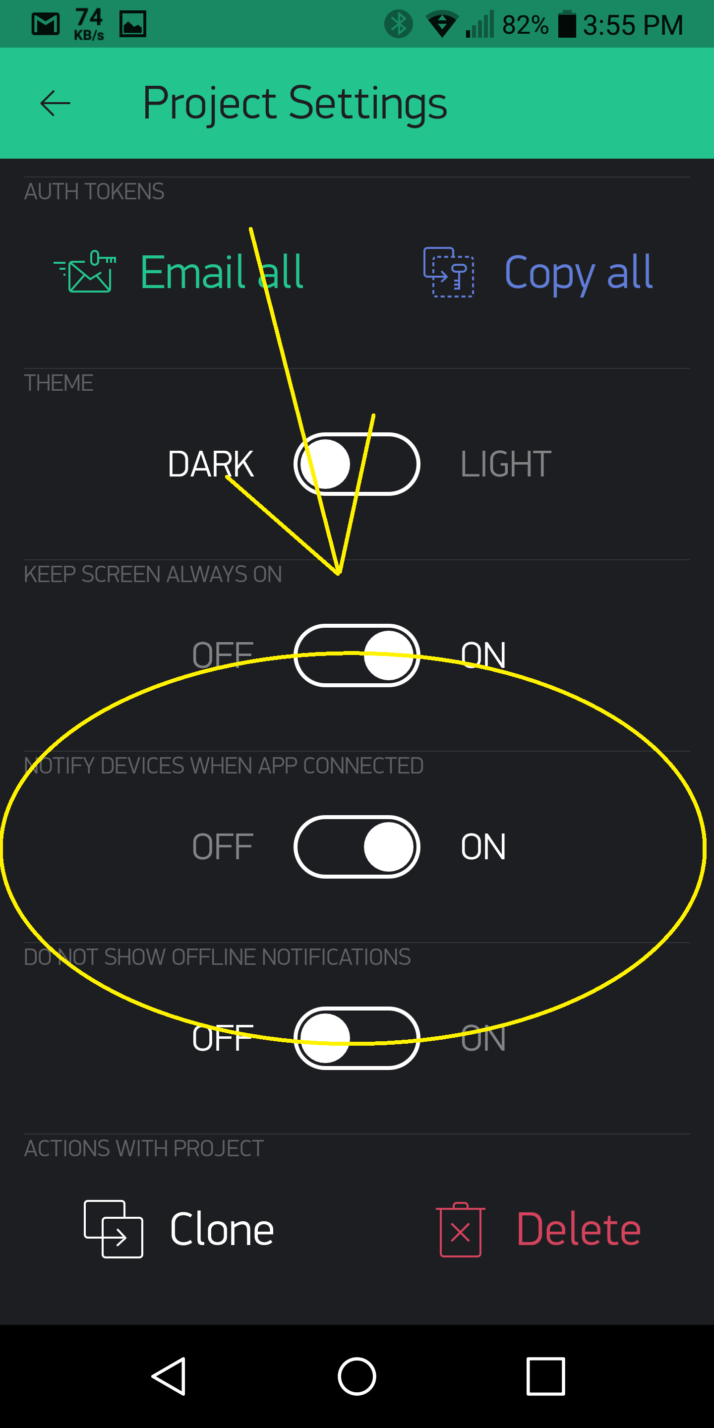
BLYNK_APP_DISCONNECTED()
This function is called every time the Blynk app disconnects from Blynk Cloud or private server.
BLYNK_APP_DISCONNECTED() {
// Your code here
}
Note: Enable this feature in Project Settings first:

Blynk.syncAll()
Requests all stored on the server latest values for all widgets. All analog/digital/virtual pin values and states will be set to the latest stored value. Every virtual pin will generate BLYNK_WRITE() event.
BLYNK_CONNECTED() {
    Blynk.syncAll();
}
Blynk.syncVirtual(vPin)
This command updates individual Virtual Pin to the latest stored value on the server. When it’s used, a corresponding BLYNK_WRITE handler is called.
Blynk.syncVirtual(V0);To update multiple pins, use:
Blynk.syncVirtual(V0, V1, V6, V9, V16);Blynk.setProperty(vPin, “property”, value)
This command allows changing widget properties
Debugging
#define BLYNK_PRINT
#define BLYNK_DEBUG
To enable debug prints on the default Serial port add on the top of your sketch IMPORTANT: This should be the first line in your code:
#define BLYNK_PRINT Serial // Defines the object that is used for printing
#define BLYNK_DEBUG        // Optional, this enables more detailed prints
Then enable Serial Output in setup():
Serial.begin(9600);Open Serial Monitor and you’ll see the debug prints.
You can also use spare Hardware serial ports or SoftwareSerial for debug output (you will need an adapter to connect to it with your PC).
WARNING: Enabling BLYNK_DEBUG will slowdown your hardware processing speed up to 10 times!
BLYNK_LOG()
When BLYNK_PRINT is defined, you can use BLYNK_LOG to print your logs. The usage is similar to printf:
BLYNK_LOG("This is my value: %d", 10);On some platforms (like Arduino 101) the BLYNK_LOG may be unavailable, or may just use too much resources.
In this case you can use a set of simpler log functions:
BLYNK_LOG1("Hello World"); // Print a string
BLYNK_LOG1(10);      // Print a number
BLYNK_LOG2("This is my value: ", 10); // Print 2 values
BLYNK_LOG4("Temperature: ", 24, " Humidity: ", 55); // Print 4 values
...
Minimizing footprint
To minimize the program Flash/RAM, you can disable some of the built-in functionality:
- Comment-out
#define BLYNK_PRINTto remove prints - Put on the top of your sketch:
#define BLYNK_NO_BUILTIN   // Disable built-in analog & digital pin operations
#define BLYNK_NO_FLOAT     // Disable float operations
Porting, hacking
If you want to dive into crafting/hacking/porting Blynk library implementation, please also check this documentation.
FAQ
I backed Blynk on Kickstarter. Where are my widgets and why the app is free?
App is free because otherwise you would have to pay to download it. This is how AppStore and Google Play works. Current Blynk release has a limited amount of widgets. We decided to make them free for everyone until we implement store. After that, every widget will be paid. However every backer will get them for free (according to their pledge).
What is Blynk Cloud?
Blynk Cloud is a open-source software written on Java using plain TCP/IP and secured TCP/IP (for hardware that supports it) sockets and running on our server. Blynk iOS and Android apps connect to Blynk Cloud by default. Access is free for every Blynk user. We also provide a Private Server distribution for those who want to install it locally.
How much access to Cloud Blynk Server cost?
It is free for every Blynk user.
Can I run Blynk server locally?
Yes. Those of you, who want extra security or don’t have internet connection, can install Local Blynk Server and run it in your own local network. Blynk Server is Open-Source and it takes less than few seconds to deploy. All the instructions and files are here.
What are the requirements to run Private Blynk Server?
To run Private Blynk Server, all you need is Java Runtime Environment.
Can I run Blynk server on Raspberry Pi?
Yes, surely! Here is instruction.
Does Blynk app work over Bluetooth?
Yes. It is in beta right now.
Does Blynk support Ethernet / Wi-FI / UART?
Yes, all of them. See full list of supported hardware and shields.
I don’t have any shield. Can I use Blynk with my computer?
Yes, you can use Blynk just with a USB cable. There is a step-by-step instruction on how to do it.
Can Blynk handle multiple Arduinos?
Yes. There 3 ways right now :
- add multiple devices to your project.
- you may use same Auth Token for different hardware. In that case you can control few hardwares from 1 dashboard.
- you can do it using Bridge functionality which allows you to send messages from one hardware to another.
Does Blynk server store sensor data when app goes offline?
Yes, every command that hardware sends to server is stored. You could use History Graph widget in order to view it.
How many Virtual Pins I can use?
It depends mostly on your hardware. Low-end hardware may use up to 32 Virtual Pins. More powerful (like ESP8266) can use up to 128 but it requires also BLYNK_USE_128_VPINS property in your sketch. Example.
Why app requires all this permissions?
http://help.blynk.cc/faq/blynk-android-permissions-explained
Links
License
This project is released under The MIT License (MIT)
